Mastering the Art of Plc Controller Wiring Diagrams
To master the art of programming PLC (Programmable Logic Controller) controller wiring diagrams, it's essential to understand the intricacies of electrical connections and how they relate to the logic of the control system. A comprehensive knowledge of the various components and their functions is critical for creating effective and efficient wiring diagrams that can accurately represent the flow of power and signals throughout the system. Additionally, a good grasp of coding skills enables engineers to translate these wiring diagrams into actual working code, ensuring that the PLC system operates smoothly and effectively. With consistent attention to detail and a willingness to learn, anyone can become adept at designing and implementing PLC wiring diagrams, ultimately leading to improved efficiency, reliability, and cost savings in industrial settings.
In this modern age where automation is a ubiquitous feature in various industries, the role of the Programmable Logic Controller (PLC) becomes all-encompassing. It's more than just a device; it's the backbone of your manufacturing processes, transportation systems, and even your home appliances that you might not have given a second glance at. And with each passing day, the need for these intelligent controllers continues to grow as they offer efficiency, accuracy, and flexibility that traditional systems can't match.
So, let’s dive into how one would go about understanding and mastering the plc controller wiring diagrams. This process involves more than just flipping through pages of text; it's akin to unraveling a complex web of wires and connections. Each step requires precision, attention to detail, and a deep understanding of electrical engineering principles.
The first thing to consider when studying a plc controller wiring diagram is its purpose. What kind of system does it represent? Is it for a simple machine tool or an intricate factory automation system? Once you understand the context, you can start piecing together the various components such as sensors, actuators, and other devices that make up the system.
Next, focus on the connections between different components. The wiring diagram will typically depict a series of lines, arrows, and symbols representing electrical connections. These connections are essential for ensuring that all the components within the system work together seamlessly. A good understanding of electrical schematics is key to troubleshooting any faulty connections or broken circuits that may arise over time.

One of the most challenging aspects of wiring a plc controller is ensuring that the system remains safe and reliable. In addition to physical connection points, there are also software considerations to take into account. The programming language used to program the PLC should align with the hardware specifications of the device being used. Moreover, proper coding practices must be followed to avoid common pitfalls like syntax errors, data corruption, and security vulnerabilities.
When working with plc controllers, one must also be aware of the environmental conditions that could affect their performance. For example, temperature, humidity, and vibration levels can all impact the reliability and lifespan of the hardware components involved. Proper ventilation and cooling solutions must be implemented to ensure optimal operating conditions.
Another critical aspect to consider is the maintenance and repair of the system. With the increasing complexity and interconnectedness of today's PLCs, it's easy to become overwhelmed by the sheer number of components involved. However, regular inspections and updates can help detect problems early on, minimizing downtime and costly repairs.
Finally, it's worth mentioning that mastering the art of plc controller wiring diagrams takes time and practice. There are countless resources available online to assist those looking to learn more about this field. From tutorials and courses to forums and certification programs, there are numerous ways to gain knowledge and expertise in this area.
In conclusion, while plc controller wiring diagrams may seem like a daunting task at first, with dedication, patience, and a willingness to learn, anyone can become proficient in this area. By understanding the various components involved, following proper coding practices, taking into account environmental factors, maintaining the system regularly, and utilizing the latest resources available, one can confidently navigate the complex world of PLC programming. So why settle for mediocrity when you have the power to create something truly exceptional?
Content expansion reading:
Content:

Hey there! If you're new to the world of PLCs (Programmable Logic Controllers), or you're just looking to brush up on your knowledge, understanding PLC controller wiring diagrams is a crucial step. These diagrams can seem intimidating at first, but once you know what to look for, they're actually pretty straightforward.
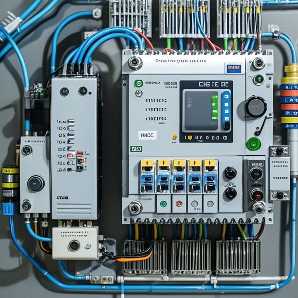
So, what exactly is a PLC controller wiring diagram? It's a visual representation of the electrical connections between the various components of a PLC system. This includes the power supply, input devices, output devices, and the PLC itself. The diagram shows you how these components are connected and how they interact with each other.
When you're looking at a PLC controller wiring diagram, the first thing you'll notice is that it's divided into different sections. The power supply section is usually at the top, followed by the input devices, the PLC, and finally, the output devices. Each section is labeled clearly, so you can easily identify what's what.
Input devices are the sensors that provide data to the PLC. They can be switches, buttons, temperature sensors, or any other device that sends a signal to the PLC. Output devices, on the other hand, are the ones that receive signals from the PLC and perform an action. These can be motors, lights, solenoids, or anything that needs to be controlled by the PLC.
The PLC itself is the brain of the system. It's where the programming takes place, and it's responsible for interpreting the input signals and deciding what to do with them. The PLC will then send output signals to the appropriate devices to control the process.
Now, let's talk about the symbols you'll see in a PLC controller wiring diagram. Each component has a specific symbol that represents it. For example, a switch might be represented by a simple on/off symbol, while a temperature sensor might have a more complex symbol that includes a thermometer.
The wires in the diagram are also color-coded to indicate their function. Power wires are typically black, while ground wires are usually green or brown. Wires that carry control signals can be any other color, and they're often labeled with their function (like "start" or "stop").

When you're reading a PLC controller wiring diagram, it's important to follow the flow of the diagram from left to right. This will help you understand the sequence of events that occur when the system is running.
If you're working with a specific PLC model, the manufacturer will provide detailed documentation and wiring diagrams. Always refer to these resources for the most accurate information. And if you're ever unsure about something, don't hesitate to reach out to a more experienced colleague or consult the manufacturer's manual.
Remember, safety is paramount when working with PLCs and electrical systems. Always ensure that the power is off before you start working on any wiring, and use the appropriate tools and safety gear.
By understanding PLC controller wiring diagrams, you're not only gaining a valuable skill but also opening up a world of opportunities in the field of automation. So, take the time to learn and understand these diagrams, and you'll be well on your way to becoming a pro in no time!
Articles related to the knowledge points of this article:
PLC Controller Selection Guide for Foreign Trade Operations
PLC (Programmable Logic Controller) Control System Basics
Connecting a PLC Controller to Your Computer
PLC Controllers: A Comprehensive Guide to Understanding Their Prices