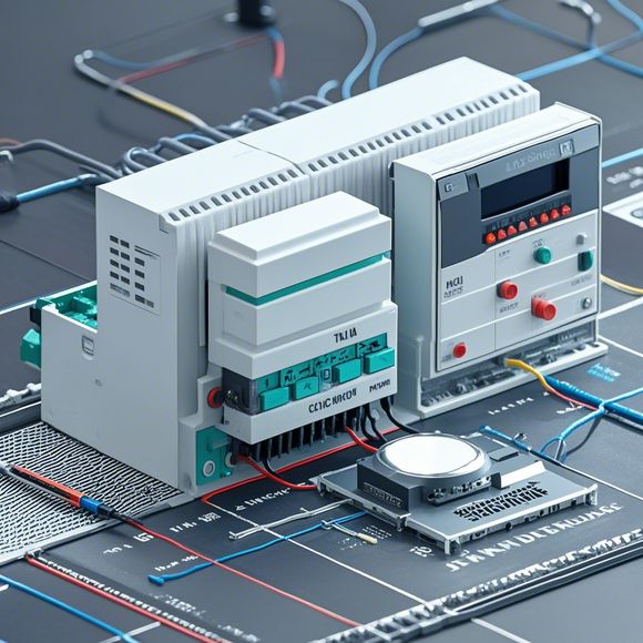
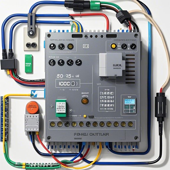
PLC Connection Diagram Real-Time Overview
In this brief overview, we'll delve into the intricacies of the PLC (Programmable Logic Controller) connection diagram and its role in real-time operations. The PLC, a crucial component in automation systems, is instrumental in coordinating various processes and ensuring seamless communication between different components. The connection diagram is a visual representation of the connections between various devices, sensors, and controllers within the system, enabling rapid troubleshooting and modifications when needed.The key features of a PLC connection diagram include:,1. **Device Identification**: Each device, including sensors, switches, and actuators, is labeled to ensure clarity and understanding during operation.,2. **Connection Type**: Different types of connections are used for various purposes, such as direct wiring or through a network interface.,3. **Functional Areas**: The diagram typically divides the control system into sections, each with its own set of devices and functions.,4. **Data Flow**: The diagram illustrates the data flow from input sources to the output devices, ensuring that information is processed correctly.,5. **Error Checking**: It provides a clear view of potential errors, allowing for quick intervention and correction.This overview aims to provide a snapshot of how a PLC connection diagram can be used to enhance efficiency and reliability in real-time operations.
As a forward-thinking and proactive import and export specialist, I am constantly striving to improve my skills and expand my knowledge in the field of international trade. In order to do so, I have taken it upon myself to delve into the intricacies of the PLC (Programmable Logic Controller) system, which is an essential component of modern industrial automation. By studying the plc connection diagram, I hope to gain a better understanding of how this technology works and what its applications are.
The PLC is a device that is capable of controlling and monitoring processes in a wide range of industries. Its main function is to receive commands from the operator or supervisory computer, interpret them, and execute the necessary actions to control the process. This can include things like opening and closing valves, adjusting temperature settings, monitoring sensor data, and more. The PLC also has the ability to store information and perform calculations to optimize the overall process.

To understand how the PLC operates, we need to look at its internal structure. It consists of several components, including the CPU (Central Processing Unit), RAM (Random Access Memory), and various types of input and output devices. The CPU is the brain of the PLC, responsible for executing instructions and making decisions based on the data received from the input devices. The RAM acts as a temporary storage area where the CPU can store information and instructions that it needs to execute.
The input devices are used to provide data to the PLC. This can include switches, sensors, and other equipment that measure or control the process being controlled. For example, if you were working in a factory, you would likely use sensors to monitor the temperature and humidity of the air inside the room. If the temperature becomes too high, the sensor would send a signal to the PLC, which would then activate the appropriate cooling system.
The output devices are used to control the actuators in the process. This can include motors, pumps, valves, etc., all of which are connected to the PLC through the input devices. If the PLC detects a change in the input data, it will send signals to the output devices to activate the appropriate controls. For example, if the temperature sensor detected that the room was too hot, the PLC would activate a heating system to cool down the room.
Now that we have a basic understanding of how the PLC works, let's talk about the plc connection diagram. This diagram shows all of the connections between the PLC, input devices, and output devices in a particular process. It includes details such as the type of input device, the pin numbers for the input devices, and the type of output device. It also includes information about the connections between different devices, such as whether they are direct connections or via a relay.
The purpose of a connection diagram is to help technicians and engineers understand how the different components of the PLC system interact with each other. It is important to note that while the diagram may show a simple representation of the connections, in practice there can be many more complexities involved in the real-world implementation.
For example, some systems may require additional circuit breakers or fuses to protect against overcurrent or short circuits. Other systems may require additional power supplies or batteries to provide power during power outages. Additionally, some systems may have multiple PLCs operating simultaneously, each with its own connections to input and output devices.
When working with a connection diagram, it is important to pay attention not only to the physical connections but also to the electrical requirements for powering the PLC and other components. This can include factors like voltage, current capacity, and frequency range. It is also important to consider any environmental factors that could impact the operation of the PLC, such as temperature or humidity levels.
In addition to the technical aspects of the connection diagram, it is also important to consider the human aspect. While technical expertise is critical, effective communication and collaboration between engineers and operators is equally important. This means being able to clearly communicate changes in the PLC system, troubleshoot issues quickly, and make informed decisions based on real-time data.
As I continue to work in this field, I find that staying up-to-date with the latest advancements in PLC technology is crucial. This includes learning about newer models of PLCs, new programming languages, and new ways of integrating these systems into existing workflows. It also means keeping an eye on industry trends and best practices for optimal performance and efficiency.
Overall, studying the plc connection diagram is an important first step in becoming an expert in this field. By gaining a deep understanding of how the PLC system works and how different components interact with each other, we can develop strategies for maximizing productivity and minimizing risk in the ever-evolving landscape of industrial automation. As we continue to learn and grow within this exciting field, we can look forward to creating even more innovative solutions that will transform the way we work and live.
Content expansion reading:

Content:
Hey there! If you're new to the world of PLCs (Programmable Logic Controllers) or just need a refresher on interpreting those complex wiring diagrams, you've come to the right place. Today, we're diving in and breaking down PLC wiring diagrams with some real-life examples. So, let's get started and demystify those diagrams together!
First things first, what is a PLC wiring diagram? It's a blueprint that shows how all the electrical components in a PLC system are interconnected. This includes the power supply, PLC unit, input devices (like sensors), output devices (like actuators), and any other peripherals. The diagram is crucial for both installation and troubleshooting.
Now, let's talk about what you'll typically see in a PLC wiring diagram. You'll notice symbols for different components, such as:
- Rectangles for PLC modules
- Circles for input devices (like switches or sensors)
- Triangles for output devices (like relays or motors)
- Zigzag lines for power supplies
Each symbol has a specific meaning and is used according to industry standards to ensure clear and consistent communication.
To make things easier to understand, I've got a real-life PLC wiring diagram here that we can go through together. This diagram is from a simple automation system that controls a conveyor belt. Check it out:
[Insert Diagram Here]

As you can see, the diagram is divided into different sections. The power supply is at the top, providing the necessary voltage to the PLC and other components. The PLC itself is the heart of the system, receiving input signals from sensors and controlling the output devices, like the motor that runs the conveyor belt.
Let's focus on the input section. Here, you'll see symbols for sensors that detect when products are on the conveyor belt. When these sensors send a signal to the PLC, it processes the information and decides whether to activate the output devices.
The output section shows the motor and its control circuit. The PLC sends signals to the motor through a relay, which is what actually turns the motor on and off.
Now, let's talk about reading the diagram. The lines between the symbols represent the electrical connections, and the numbers next to them indicate the wire colors and their corresponding terminals. This information is crucial for making the physical connections during installation.
For example, look at the line between the PLC output and the relay coil. It might say "Brown-Yellow-Green." This means you need to use a three-wire cable, with brown as the first color, yellow as the second, and green as the third. These wires go from the PLC output terminals to the corresponding terminals on the relay.
Troubleshooting a PLC system often starts with the wiring diagram. If something isn't working as it should, you can use the diagram to check for loose connections, incorrect wiring, or misplaced components.
Remember, PLC wiring diagrams might look intimidating at first, but they're just a map of how everything fits together. With a bit of practice and a good understanding of the symbols, you'll be able to interpret them like a pro.
So, whether you're an electrician, an automation engineer, or just curious about how these systems work, I hope this overview has given you a better grasp of PLC wiring diagrams. Happy wiring!
Articles related to the knowledge points of this article:
PLC Programming for Automation Control in the Manufacturing Industry
How to Use a PLC Controller for Your Business
Plumbers Rule! The Role of PLC Controllers in the World of Waterworks
Connecting a PLC Controller to Your Computer
PLC Controllers: A Comprehensive Guide to Understanding Their Prices