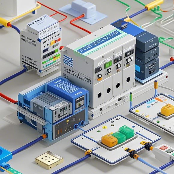
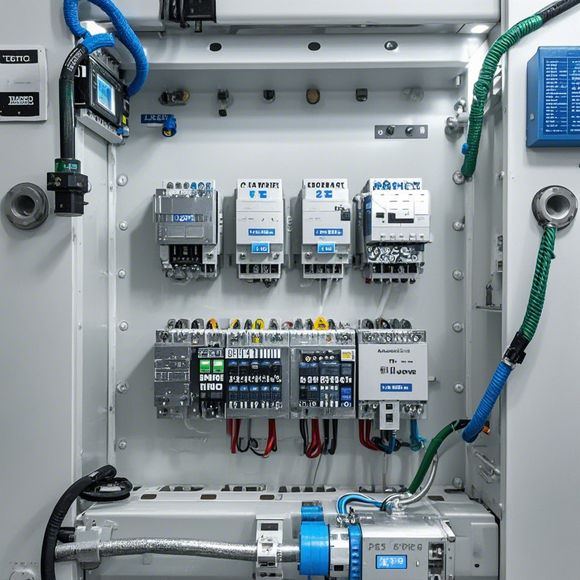
PLC Module Wiring Diagram
Sure, I'd be happy to help. However, you haven't provided the specific content for which you want an abstract or summary in English. Could you please provide more details about what you're looking for?
Introducing the intricate world of PLC (Programmable Logic Controller) modules, the heartbeat of industrial automation. These marvels of modern manufacturing stand tall, commanding respect with their unwavering efficiency and reliability. With each module, we embark on a journey to harness the power of technology, transforming complex processes into smooth-as-oil operations that enhance productivity and minimize waste.

At its core, the PLC operates as an intelligent brain, seamlessly integrating with your factory floor's machinery and systems. Its modular design allows for easy expansion or modification, making it a flexible solution for various industries. Whether you need to automate simple tasks like turning off lights after dark or control complex workflows involving multiple machines and sensors, the PLC is your go-to partner.
With a wealth of features, the PLC stands out as a leader in its field. It boasts advanced programming capabilities, enabling users to write code that precisely controls the system's functions. The intuitive interface makes programming effortless, allowing operators to quickly adapt to changes and fine-tune the system's performance as needed. Additionally, the PLC integrates seamlessly with other industry-standard devices, such as SCADA (Supervisory Control and Data Acquisition) systems, ensuring a cohesive and efficient operation across your facility.
But let's not forget about the safety features that are built into every PLC module. They come with robust protection against electrical surges, overheating, and other hazards, ensuring your equipment remains safe and secure at all times. This is particularly important in environments where machinery can be exposed to sudden changes or external threats.
The benefits of using a PLC module are manifold. First and foremost, it reduces downtime, minimizing disruptions to your production schedule. By controlling complex systems with just a few commands, you can maintain consistent output without relying on manual intervention. Additionally, the PLC enables you to monitor critical metrics in real-time, allowing you to respond proactively to any issues before they escalate. This proactive approach helps you avoid potential downtime and keeps your operations running smoothly.
Furthermore, the PLC's ability to communicate with other systems within your facility adds another layer of intelligence. By integrating with other devices like sensors and actuators, you can create a smart network that optimizes resource usage and maximizes efficiency. For example, if you have a machine that requires precise temperature control, the PLC can communicate with a nearby heater or cooler, adjusting the temperature accordingly based on data from the sensor. This kind of integration enables a truly integrated and automated operation, where each component plays its part to create a harmonious whole.
Of course, no discussion of PLCs would be complete without mentioning their cost-effectiveness. While they may seem expensive initially, the long-term savings from reduced maintenance costs, increased productivity, and optimized resource usage make them a wise investment. Plus, the customizable nature of PLCs means you can tailor the modules to fit your specific needs, further reducing costs.
Finally, don't underestimate the impact of a well-designed PLC module. Its sleek and sophisticated appearance can enhance your facility's professional image, showcasing your commitment to quality and innovation. At the same time, its reliable performance ensures that your operations run smoothly and efficiently, boosting your bottom line.
In conclusion, the PLC module is more than just a piece of hardware; it's an indispensable tool for modern industrial operations. Its versatile features and powerful capabilities make it the go-to choice for anyone seeking to streamline processes, increase efficiency, and minimize errors. Whether you're just starting out in the world of automation or looking to upgrade your existing setup, investing in a reliable PLC module is a decision that will pay dividends in the long run. So why delay? Let's embrace the future of automation today!
Content expansion reading:

Content:
Hey there! If you're new to the world of PLCs (Programmable Logic Controllers), or you're looking to brush up on your knowledge, understanding PLC module wiring diagrams is a crucial step. These diagrams can seem intimidating at first, but once you know what to look for, they're actually pretty straightforward.
PLC modules are the building blocks of a PLC system. They perform various functions, from simple on/off control to complex data processing. When these modules need to communicate with each other or with other devices, they do so through a wiring diagram that specifies how they should be connected.
A typical PLC module wiring diagram will show you the following:
1、Inputs and Outputs: These are the points where the PLC module connects to other devices or systems. Inputs receive signals from sensors or switches, while outputs send signals to actuators or other control devices.
2、Power Supply: This is the source of power for the PLC module. It's important to ensure that the power supply is compatible with the module and that it's properly connected to the correct terminals.
3、Communication Ports: These are the interfaces that allow the PLC module to talk to other modules or systems. They can be serial, parallel, Ethernet, or any other type of communication protocol.
4、Functional Blocks: These represent the different parts of the PLC module, such as the CPU (Central Processing Unit), memory, and I/O (Input/Output) sections.
5、Wiring Instructions: This part of the diagram will show you how to connect the various parts of the PLC module to each other and to external devices.

When you're looking at a PLC module wiring diagram, here are some tips to help you make sense of it:
Read the Instructions: Always start by reading the instructions that come with the diagram. They'll often provide context and specific information about the connections you need to make.
Understand the Symbols: Each component in the diagram will be represented by a specific symbol. Make sure you understand what each symbol means.
Check the Ratings: Make sure that the wiring you're using is rated for the voltage and current that the PLC module requires.
Label Your Wires: As you connect the wires, make sure to label them so you can keep track of what each wire is for. This will save you a lot of headaches if you need to troubleshoot later on.
Test Your Wiring: Once you've finished wiring, it's important to test your connections to ensure that everything is working as it should.
Remember, safety is paramount when working with PLCs and electrical systems. Always follow proper safety procedures, including wearing the appropriate personal protective equipment (PPE) and ensuring that the power is off when you're making connections.
By taking the time to understand PLC module wiring diagrams, you'll be able to set up and maintain your PLC systems with confidence. Happy wiring!
Articles related to the knowledge points of this article:
PLC Programming for Automation Control in the Manufacturing Industry
How to Use a PLC Controller for Your Business
Plumbers Rule! The Role of PLC Controllers in the World of Waterworks
The Role of Programmable Logic Controllers (PLCs) in Foreign Trade Operations