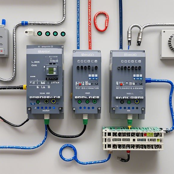
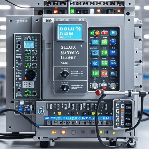
plc接线图实物图
Certainly! Let's break down your request into a summary in plain English.---**Summary:**To create a PLC (Programmable Logic Controller) schematic and physical drawing, you will need to follow these steps:1. **Design the Schematic:** Use a software such as KiCad or Ladder Diagram Studio to design the circuit diagram that represents the connections between various components in the PLC. Ensure all wiring is correctly labeled and labeled with appropriate symbols for clarity.2. **Prepare the Physical Drawing:** Once the schematic is complete and approved, proceed to physically draw the schematic onto paper using standardized symbols. This step requires precision and attention to detail, especially when dealing with complex connections.3. **Testing:** After completing the physical drawing, test it by connecting all components according to the schematic. Make sure all connections are correct and function properly before moving on to the next stage.4. **Review and Modifications:** If any errors or discrepancies arise during testing, make revisions to the schematic and physical drawing accordingly. This process ensures that the final product is error-free and meets all specifications required by the PLC system.5. **Final Review and Packaging:** Once satisfied with the final product's accuracy and quality, package it for shipping or installation. This step involves ensuring the drawings and components are securely packaged and ready for use.---This summary provides a basic overview of how to create a PLC schematic and physical drawing. Remember to keep in mind any specific requirements or guidelines provided by your PLC manufacturer for optimal results.
"Interfacing PLCs for Optimal Control Systems in the Modern Manufacturing Era"
Hey guys, I've been tasked with discussing the intricate world of PLC (Programmable Logic Controller) interfacing. So, let's dive right into the details. Imagine you have a factory that's churning out some high-quality products, and you're using a set of PLCs to control everything, right? Well, if you're not sure how these ol' controllers work, it can feel like trying to unpack a box of Lego without any instructions – a little bit overwhelming!
But don't worry, we'll break this down step by step. Firstly, there are two main types of PLCs: DCS (Distributed Control System) and PID (Proportional Integral Derivative). Each has its own unique capabilities, but they all serve a common purpose: to make your manufacturing processes run as smoothly as possible.
Now, let's talk about the first step in the interfacing process – connecting your PLC to the power source. This might seem straightforward enough at first glance, but there are a few key considerations to keep in mind. For example, you want to make sure that the voltage levels on both sides match up properly. If they don't, your PLC could fry, and that's not what you want!

Another important aspect is ensuring that the wiring is secure and doesn't come loose over time. This means using quality connectors and cables that can withstand the wear and tear of everyday use. After all, you don't want your hard-earned money going to waste on a product that won't last long!
Of course, once you've got everything hooked up, the next step is to program your PLC. This can be done using various programming languages, such as ladder logic, function blocks, or even directly in the PLC language itself. It's important to choose a language that makes sense for your specific project, as different languages have their strengths and weaknesses when it comes to performance and ease of use.
Once you've programmed your PLC, the final step is to test it thoroughly before putting it into production. This includes verifying that all functions work as expected, testing for errors and bugs, and making sure that the system can handle unexpected situations without crashing.
So, there you have it – the basics of how to get started with PLC interfacing for your modern manufacturing needs. Remember, it may seem daunting at first, but with the right tools and techniques, anyone can turn their PLCs into powerful tools for streamlining their operations and improving efficiency.
Content expansion reading:
Content:
Hey there! If you're new to the world of PLCs (Programmable Logic Controllers) or just need a refresher on interpreting those complex wiring diagrams, you've come to the right place. Today, we're diving in and breaking down PLC wiring diagrams with some real-life examples. So, let's get started and demystify those diagrams together!
First things first, what is a PLC wiring diagram? It's a blueprint that shows how all the electrical components in a PLC system are interconnected. This includes the power supply, PLC unit, input devices (like sensors), output devices (like actuators), and any other peripherals. It's essential for ensuring that your PLC system is installed and functioning correctly.
Now, let's talk about what you'll typically see in a PLC wiring diagram. You'll notice symbols for different components, such as:
- Power supply: This is the source of electricity for your PLC system. It's usually a DC or AC power supply unit.

- PLC unit: The heart of the system, where all the logic and decision-making happen.
- Input devices: These are the eyes of the system, like limit switches, proximity sensors, or push buttons, that provide data to the PLC.
- Output devices: These are the muscles, devices like motors, solenoids, or lights that the PLC controls.
- Relays and contactors: These are switches that control power in the system.
To make sense of all these symbols, you need to understand the language of the diagram. Each component is represented by a specific symbol, and the lines connecting them show the flow of electricity or data. The direction of the lines and the presence of arrows indicate the direction of current flow or the path of data transmission.
Let's look at a simple PLC wiring diagram. Imagine you've got a basic setup with a power supply, PLC, input sensor, and an output actuator. The power supply is connected to the PLC, which is then connected to the input sensor. When the sensor detects a certain condition, it sends a signal to the PLC, which processes the information and decides whether to activate the output actuator. The PLC wiring diagram would show all these connections, making it clear how everything fits together.
Now, let's talk about reading a more complex PLC wiring diagram. You might have multiple inputs and outputs, and the PLC might be controlling several different processes simultaneously. The key is to take it step by step. Start by identifying the power supply and tracing the lines to the PLC. Then, look for inputs and outputs, and follow the connections to understand how they interact with the PLC.
Remember, practice makes perfect. The more wiring diagrams you study, the better you'll become at interpreting them. And don't be afraid to ask questions or seek help from more experienced colleagues.
In conclusion, PLC wiring diagrams can seem intimidating at first, but with a bit of knowledge and practice, you'll be able to understand them like a pro. Always keep in mind that these diagrams are there to guide you, so take the time to learn their language, and you'll be able to troubleshoot and maintain your PLC systems with ease. Happy diagramming!
Articles related to the knowledge points of this article:
PLC Programming for Automation Control in the Manufacturing Industry
How to Use a PLC Controller for Your Business
Connecting a PLC Controller to Your Computer
PLC Controllers: A Comprehensive Guide to Understanding Their Prices