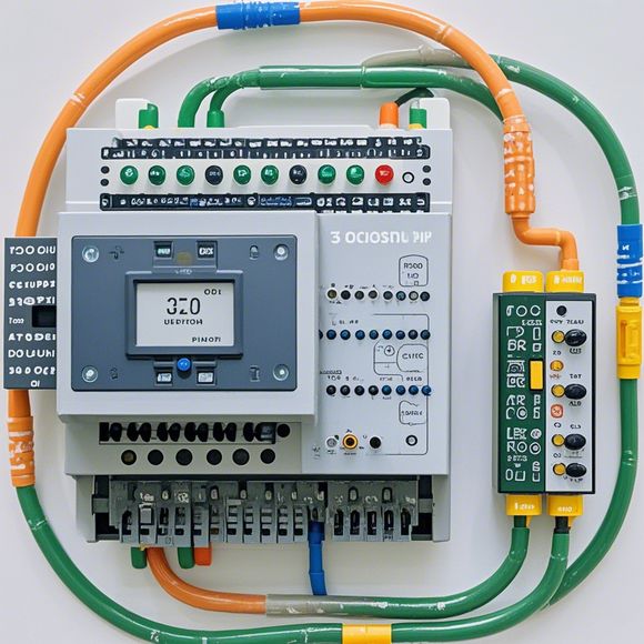
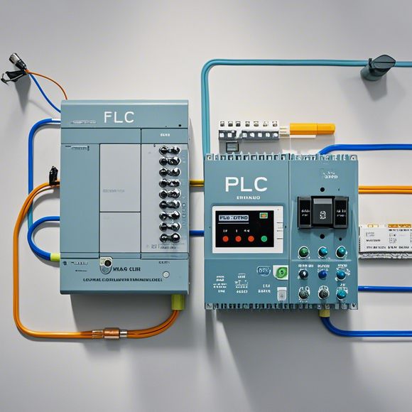
PLC Control System Principle Diagram
Certainly, based on the content you've provided, here is a concise summary in spoken English:The PLC Control System Principle Diagram is an illustration that depicts how the Programmable Logic Controller (PLC) operates. It outlines the basic structure and functions of a PLC system. The Diagram typically includes blocks for input/output interfaces, logic control functions, and data processing capabilities. It also shows how these components interact with each other to achieve specific control tasks. By analyzing the Diagram, one can understand the overall flow of signals and actions within the PLC system, which is crucial for troubleshooting, programming, and maintaining the system's efficiency.
As a foreign trade operations professional, understanding the fundamentals of the Programmable Logic Controller (PLC) control system is crucial for effectively managing and operating industrial equipment. Here's an overview of how to structure your content based on the PLC system principle diagram in English:

Introduction
In today's manufacturing landscape, the PLC (Programmable Logic Controller) has become a ubiquitous technology that drives the automation of industrial processes. The PLC serves as the brain of these systems, processing inputs from various sensors and actuators to produce output signals that can directly control the machinery and devices within the plant. This document outlines the essential components of a typical PLC system, their functions, and how they interconnect to create a functional control network.
Components of a PLC System
1、Processor Unit: The brain of the PLC, it executes programming stored in memory chips and performs calculations to generate control signals. The processor unit is often referred to as the CPU (Central Processing Unit).
2、Input/Output Modules: These modules are responsible for receiving data from external sources such as sensors, switches, or other input devices, and transmitting them to the CPU via digital or analog signals.
3、Memory: The main memory stores the PLC program code, which the CPU reads during startup and execution.
4、Power Management Unit (PMU): This unit ensures that the PLC operates with minimal power consumption while ensuring that all circuitry operates correctly. It manages the power supply to the various modules and circuits in the PLC.
5、Communication Interfaces: These interfaces allow the PLC to communicate with other devices within the plant network, such as other control systems or external devices like printers or display screens.
6、Networking Elements: In larger plants, the PLC may be part of a distributed control system where multiple PLCs work together to control a complex system. Networking elements help these PLCs communicate with one another.
7、Sensors and Actuators: These are connected to the PLC through I/O modules, enabling the PLC to monitor and control various parameters in real-time.
8、Switches: These components control the status of various systems and circuits in the plant. They can be manual or automatic, depending on the application.
9、Safety Features: Many PLC systems include safety features to prevent electrical fires or other hazards. These might include circuit breakers, ground fault protection, and overload protection.
10、User Interface: A user interface provides a way for operators to interact with the PLC system and view information about the current system state and settings.
Functions of a PLC System
The primary function of a PLC is to process and manage data received from various sources, then produce appropriate responses based on those data to control and operate machinery and equipment. Here are some key functions:
1、Data Acquisition: Collects information from various sensors, switches, and other input devices.
2、Process Control: Processes the collected data to determine what actions need to be taken to maintain or optimize the operation of the machinery.
3、Device Interaction: Sends commands to actuators to control motors, valves, pumps, etc., based on the processed data.
4、Error Detection and Handling: Monitors for errors, such as faults in sensors or equipment failures, and automatically initiates corrective actions if necessary.
5、System Diagnostics: Maintains a log of system activity, including when and why certain events occurred, to aid in troubleshooting and maintenance tasks.
6、Security and Compliance: Ensures that the system complies with regulatory requirements and protects sensitive data from unauthorized access.
Interconnection and Communication
The communication between different components in a PLC system is critical for its functionality. The following steps outline the basic communication flow:
1、Data Flow: From the sensors and actuators, data is sent to the PLC via the I/O modules.
2、Processing: The PLC’s CPU processes this data and generates control signals based on these processed values.
3、Transmission: The processed signals then go through the communication interfaces to send them to other parts of the system or external devices.

4、Feedback: In many systems, feedback loops are implemented to adjust control actions based on actual system conditions.
5、Networking: For larger plants with distributed control systems, the PLCs communicate with each other through network connections, allowing coordinated control of multiple systems.
Application Scenarios
The PLC control system is used in a variety of industries and applications, including:
- Manufacturing: Controlling assembly lines, conveyor systems, and other machinery.
- Energy Generation: Controlling steam and electric generators, as well as maintaining the integrity of power systems.
- Healthcare: Controlling medical equipment, monitoring patient conditions, and providing medication administration systems.
- Automation: Automating warehouse operations, inventory management, and more.
- Agriculture: Controlling irrigation systems, harvesting machines, and other farm equipment.
Conclusion
The PLC control system plays a vital role in modern industrial environments by automating and controlling complex processes. By understanding its components, functions, and communication methods, businesses can leverage this powerful technology for improved efficiency, productivity, and operational reliability throughout their facilities.
Content expansion reading:
Content:
Hey there! If you're new to the world of PLCs (Programmable Logic Controllers), or you're looking to brush up on your knowledge, understanding PLC control system wiring diagrams is a crucial step. These diagrams can seem intimidating at first, but once you know what to look for, they're actually pretty straightforward. Let's dive in and break down the basics together!
First things first, what is a PLC control system wiring diagram? It's a visual representation of the electrical connections and components in a PLC system. It shows how the various parts of the system are interconnected, including input devices, output devices, and the PLC itself. Think of it like a blueprint for how your system communicates and operates.
When you're looking at a PLC control system wiring diagram, you'll typically see a few key components:
1、Input Devices: These are the sensors or switches that provide data to the PLC. They can detect the presence of an object, temperature changes, or any other type of physical input. Examples include limit switches, proximity sensors, and thermocouples.
2、Output Devices: These are the devices that receive instructions from the PLC and perform an action. They can control motors, valves, lights, or any other device that needs to be turned on or off in response to the program running in the PLC.
3、PLC: The heart of the system, the PLC is a small computer that processes the input data and decides what to do with it. It does this by running a program that you or someone else has created.
4、Power Supply: This component provides the electrical power necessary for the PLC and other devices in the system to operate.
5、Wires and Connectors: These are the physical connections that carry the electrical signals between the components.
Now, let's talk about how to interpret these diagrams. The key is to understand the symbols used. Different manufacturers may use slightly different symbols, but the concepts are the same. Input and output devices are usually represented by their specific type (like a photoeye or a solenoid valve), while the PLC and power supply may have specific symbols as well.
Once you know what each symbol means, you can start to make sense of the diagram. The wires will show you how everything is connected, and the numbers or letters next to the wires often indicate the specific input or output points on the PLC.
It's also important to note that PLC control system wiring diagrams often include safety features, like emergency stop buttons or interlock switches. These are designed to prevent accidents and ensure that the system is safe to operate.
In summary, PLC control system wiring diagrams are a vital tool for understanding how a PLC system is put together and how it functions. By familiarizing yourself with the symbols and components, you'll be able to troubleshoot issues, make repairs, and even modify the system if needed. So, grab a diagram and start exploring – the more you look, the easier it will become to read between the lines!
Articles related to the knowledge points of this article:
PLC (Programmable Logic Controller) Control System Basics
Plumbers Rule! The Role of PLC Controllers in the World of Waterworks
PLC Controllers: A Comprehensive Guide to Understanding Their Prices
Effective Strategies for Handling PLC Control System Faults
What is a Programmable Logic Controller (PLC)
Mastering the Art of PLC Control: Unlocking Industry-Grade Automation Powerhouses