PLC Controller Wiring Diagram for Export-Focused Business
Sure, I can generate a concise summary based on your content. Here’s a brief overview in English:For businesses that are highly focused on exporting, it is crucial to have a well-designed PLC (Programmable Logic Controller) wiring diagram. This diagram will help ensure that the electrical connections between different components of the system are properly arranged and function correctly. It will also help identify any potential issues or risks early on, before they can cause serious problems down the line. By following the guidelines set forth in this diagram, you can create an efficient and reliable system that meets all export standards.
Hello everyone,

I hope you're all doing well! As a dedicated exporter and an integral member of your team, I wanted to share with you the importance of having a comprehensive understanding of the plc (programmable logic controller) controller wiring diagram.
The plc controller is the heart of any manufacturing or industrial automation system, and its proper functioning is crucial for the success of your business. Therefore, it's important that you have a clear picture of how the various components are connected and how they interact with each other. This wiring diagram serves as a blueprint for understanding the workings of your system, making it easier to troubleshoot any issues that may arise.
Firstly, let me give you a brief overview of what a plc controller is. It's a digital device that controls the flow of electricity in a manufacturing environment, allowing for precise movements of machines and equipment. It can be used to automate a range of processes, from simple tasks like turning on lights to more complex operations such as feeding raw materials into a production line. The beauty of a plc controller lies in its ability to respond to changes in input signals quickly and accurately, making it ideal for use in industries where speed and precision are key.
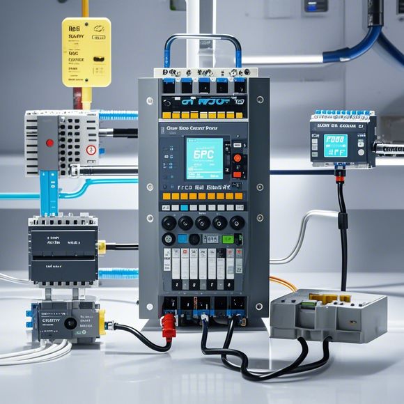
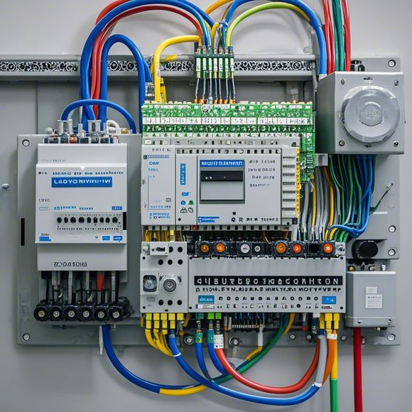
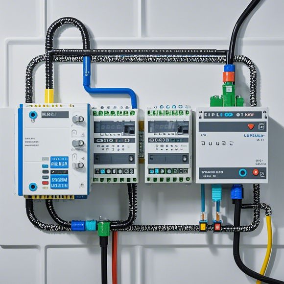
Now, onto the wiring diagram. It is a detailed map that shows how different components are interconnected in your PLC system. Each component has specific connections that must be made according to the instructions provided in the manual. These connections form a complex network that allows for communication between the various devices within the system. Without this network, your system would be unable to function effectively.
For example, if you have a machine that requires a certain amount of power to run smoothly, you would connect a power source to the appropriate outlet on the plc controller. Then, you would route the wires from the power source through the appropriate channels in the wiring diagram, connecting them to the appropriate terminals on the plc controller. This is where the real magic happens – the wires are transformed into a network that can control the flow of electricity in your system.
Of course, this isn't always easy to do by hand. In some cases, professional electrical workers may need to use specialized tools such as crimpers and connectors to make these connections. But even with their help, there's still a risk of mistakes being made. That's why it's so important to follow the instructions carefully and ensure that every connection is done correctly.
Another thing to keep in mind is the importance of testing your system before going live. This means running simulations or tests to verify that everything is operating as expected. If something goes wrong during this process, you can catch it early on and take corrective action before the system is deployed in production.
In addition to these technical details, there are also many other factors you should consider when designing your plc controller wiring diagram. For instance, you should factor in the potential for future expansion, so that your system can grow with you without having to redesign everything. You should also consider the safety of your employees when designing your wiring, ensuring that no part of the system poses a risk to them.

Finally, don't forget to keep your wiring diagram up-to-date with any modifications or upgrades to your system. Technology advances rapidly, and it's important that you stay ahead of the curve by regularly reviewing and updating your wiring diagram.
In conclusion, having a comprehensive understanding of the plc controller wiring diagram is essential for anyone looking to build and operate an efficient and reliable industrial system. By following the steps outlined above, you can ensure that your system functions flawlessly and meets all of your company's goals and needs. So go ahead and start planning your own custom wiring diagram today!
Content expansion reading:
Content:
Hey there! If you're new to the world of PLCs (Programmable Logic Controllers), or you're just looking to brush up on your knowledge, understanding PLC controller wiring diagrams is a crucial step. These diagrams can seem intimidating at first, but once you know what to look for, they're actually pretty straightforward.
So, what exactly is a PLC controller wiring diagram? It's a visual representation of the electrical connections between the various components of a PLC system. This includes the power supply, the PLC itself, input devices, output devices, and any other peripherals. The diagram is designed to help you understand how each component is connected and how the system works as a whole.
When you're looking at a PLC controller wiring diagram, the first thing you'll notice is that it's divided into different sections. These sections represent the different parts of the system, such as the power supply, input modules, output modules, and the PLC processor. Each section will have its own set of wires and connections.
Power Supply: This is where the magic starts. The power supply provides the electrical power that the PLC and its components need to operate. It's usually a separate unit that converts standard AC power to the DC power that the PLC requires. The wiring diagram will show you how the power supply is connected to the PLC and any other devices that need power.

Input Modules: These are the devices that send signals to the PLC. They can be switches, sensors, or any other device that tells the PLC what's happening in the system. Input modules are typically connected to the PLC through a series of wires that are represented in the wiring diagram.
Output Modules: Output modules receive signals from the PLC and use them to control devices such as motors, lights, or other types of actuators. Just like input modules, they're connected to the PLC via wires, and the wiring diagram will show you how they're hooked up.
PLC Processor: The heart of the system, the PLC processor is where all the decision-making happens. It's responsible for interpreting the input signals and controlling the output devices accordingly. The wiring diagram will show how the PLC is connected to the power supply, input, and output modules.
Now, here's a pro tip: When you're looking at a PLC controller wiring diagram, always start from the power supply and work your way through the diagram. This will help you understand the flow of power and information through the system.
Remember, PLC controller wiring diagrams are a tool to help you understand how a system is put together. They're not just for show; they're essential for troubleshooting, maintenance, and expansion. So, take the time to learn how to read them, and you'll be well on your way to becoming a PLC pro!
Articles related to the knowledge points of this article:
PLC Controller Selection Guide for Foreign Trade Operations
The cost of a PLC Controller: A Comprehensive Analysis
PLC Programming for Automation Control in the Manufacturing Industry
How to Use a PLC Controller for Your Business
PLC (Programmable Logic Controller) Control System Basics
Plumbers Rule! The Role of PLC Controllers in the World of Waterworks