PLC Physical Wiring Guide: A Comprehensive Guide for Beginners and Pros
"Physical Wiring Guide for Programmable Logic Controllers": A comprehensive guide for beginners and pros. This book is designed to provide a detailed overview of how to wire your PlC, whether you are a seasoned engineer or just starting out. From understanding the basics of PlC programming to troubleshooting common issues, this guide will walk you through the process step by step. With clear illustrations and easy-to-follow instructions, this book is perfect for anyone who wants to master the intricacies of PlC wiring. So grab a copy today and get ready to take your PlC skills to the next level!"
As a seasoned外贸运营, I understand the importance of accurate and efficient PLC (Programmable Logic Controller) physical wiring. It not only ensures the reliability and safety of your industrial automation system but also helps you save time and resources in setting up and maintaining your systems. In this guide, I will share with you the essential knowledge and techniques for connecting various components to your PLC, including sensors, switches, motor drives, and more. Whether you are a beginner or a professional, this guide will provide you with the tools and insights you need to achieve optimal results in your industrial applications.
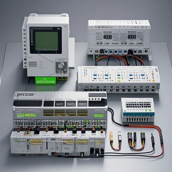
Firstly, let's start with the basics of PLC wiring. The key components that make up your PLC include the CPU, input/output modules, communication interfaces, and power supply units. When connecting these components, it's important to ensure that all connections are securely made using appropriate cables and connectors. For example, use high-quality wires and connectors for long runs of cables to prevent interference and reduce the risk of damage. Additionally, be mindful of the placement of the PLC and avoid direct sunlight or moisture exposure, as these conditions can damage the electronic components.

Now, let's dive deeper into the specific wiring configurations for each component on your PLC.
Sensors are one of the most common components used in PLC applications to detect changes in temperature, pressure, or motion. When connecting sensors, it's important to ensure that they are properly grounded to prevent false readings. For example, if you have a temperature sensor that measures temperature changes, connect the sensor to the PLC through a dedicated temperature input module. Additionally, consider using a signal amplifier circuit to improve the sensitivity and accuracy of your measurements.
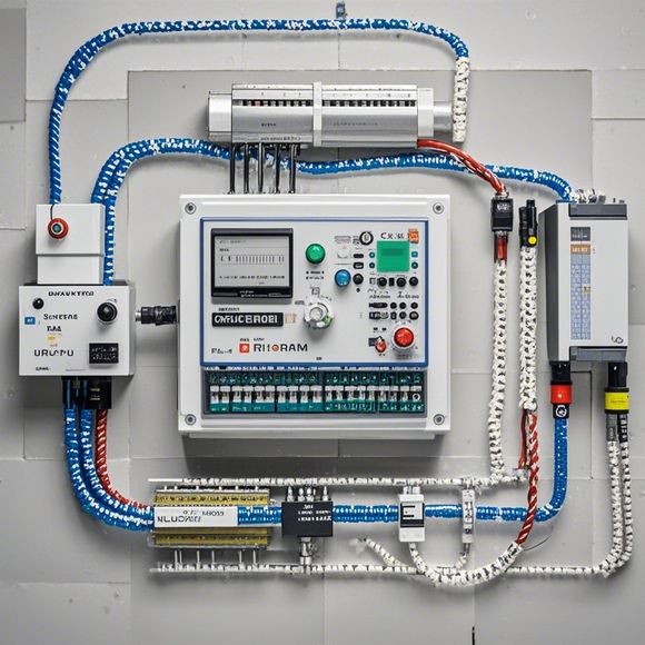
Switches are another essential component in PLC applications that control various processes based on user inputs or predefined conditions. When connecting switches to your PLC, ensure that they are correctly labeled and labeled according to their function. For example, if you have a light switch connected to the PLC, label the wires accordingly so that other engineers can easily identify them. Additionally, consider adding a relay module to protect your PLC from overload and provide an additional output signal for controlling external equipment.
Motors are often used in industrial automation applications to drive mechanical systems such as conveyor belts or pumps. When connecting motors to your PLC, it's important to choose the right type of motor driver module based on the speed and load requirements of your system. For example, if you have a low-speed motor that requires a constant voltage supply, use a PWM (Pulse-Width Modulation) controller module to adjust the duty cycle of the output signal. Additionally, consider adding a limit switch or motion sensor to monitor the position or speed of the motor and provide feedback to the PLC for better control performance.
Communication interfaces such as RS232, RS485, or Ethernet are used to connect your PLC to external devices such as computers or printers. When configuring these interfaces, ensure that you have the correct drivers installed and tested for your specific hardware setup. Additionally, consider implementing network security measures such as encryption and authentication protocols to protect sensitive data during transmission.
Power supply units are essential components that provide the necessary energy to operate your PLC and other components within the system. When connecting power supply units, it's important to ensure that they are correctly rated for the current and voltage requirements of your system. Additionally, consider adding a surge suppressor or fuse block to protect your system from unexpected power surges or short circuits.
Finally, it's essential to regularly test and maintain your PLC physical wiring to ensure its reliability and effectiveness. This includes checking for any loose connections, damaged wires, or corrosion on the terminal blocks or connectors. Additionally, consider replacing worn out cables and connectors regularly to prevent potential failures and ensure optimal performance throughout the life of your system.
In conclusion, understanding how to physically connect different components to your PLC is crucial for successful industrial automation. By following the tips and recommendations outlined above, you can establish a reliable and efficient wiring scheme that delivers accurate and reliable results every time. Remember, investing in proper wiring practices can save you time and money in the long run by preventing costly downtime due to faulty wiring systems. So take the time to educate yourself on the best practices for connecting various components to your PLC, and you'll be well on your way to achieving your industrial automation goals.
Content expansion reading:
Content:
Hey there! If you're new to the world of programmable logic controllers (PLCs) and feeling a bit overwhelmed by the thought of wiring them up, you've come to the right place. Today, we're going to dive into the basics of PLC wiring diagrams and make this topic as approachable as possible. So, grab a cup of coffee, and let's get started!
First things first, what is a PLC? Essentially, it's a type of industrial computer designed to control and automate various electromechanical processes. They're tough, they're reliable, and they can handle the harsh conditions of a manufacturing environment.
Now, let's talk about wiring diagrams. These are the blueprints that tell you how to connect all the different components of a PLC system. They're crucial for ensuring that your PLC works correctly and safely. Here's what you need to know:

1、Power Supplies: Your PLC needs power to run, and this is where the power supply comes in. It converts the incoming AC voltage to the DC voltage that the PLC can use. Always check the specifications of your PLC to ensure you're using the correct power supply.
2、Inputs: These are the devices that send signals to the PLC. Think of sensors, switches, and any other device that tells the PLC what's going on in the real world. Inputs are usually wired to the PLC's input terminals.
3、Outputs: On the flip side, outputs are the devices that the PLC controls. This could be anything from motors and actuators to lights and alarms. Outputs are connected to the PLC's output terminals.
4、Relays and Contactors: These are the workhorses that can handle high current loads. They're like switches that the PLC can turn on and off to control the flow of electricity.
5、Displays and Control Panels: These are the user interfaces that allow you to interact with the PLC. They can show you what the PLC is doing and sometimes even let you change its settings.
6、Wiring Schematics: This is where the magic happens. Wiring schematics are diagrams that show how all these components are connected to the PLC. They use standard symbols for each component, making them easy to read and understand.
When you're looking at a wiring diagram, here are some key things to look for:
Terminal Numbers: Each terminal on a PLC has a specific number. Make sure you connect wires to the correct terminals.
Wire Color Coding: Wires are often color-coded to indicate their function. For example, red wires might be used for power, black for ground, and various colors for different types of inputs and outputs.
Diagram Symbols: Learn the symbols for each component so you can follow the diagram easily.
Remember, safety is paramount when working with PLCs and electrical systems. Always follow the manufacturer's guidelines and consult with a professional if you're unsure about anything.
So, there you have it—a beginner's guide to PLC wiring diagrams. It might seem like a lot to take in, but with a bit of practice and patience, you'll be reading and creating these diagrams like a pro. Happy wiring!
Articles related to the knowledge points of this article:
PLC Controller Wiring Guideline
The cost of a PLC Controller: A Comprehensive Analysis
PLC (Programmable Logic Controller) Control System Basics
Plumbers Rule! The Role of PLC Controllers in the World of Waterworks
The Role of Programmable Logic Controllers (PLCs) in Foreign Trade Operations