Introduction to PLC Wiring Diagrams and Their Application in Modern Manufacturing
Sure, I can generate a summary in English for you. Here’s a rough draft:PLC wiring diagrams are crucial tools for modern manufacturing. They represent the electrical connections between various components of a control system. These diagrams help in understanding how different devices communicate with each other, and how they interact within the production line. PLC wiring diagrams are typically used in factories where precise control of machines is required. They allow technicians to troubleshoot issues and make adjustments quickly. The use of PLCs has significantly improved efficiency and productivity in manufacturing operations. In addition to industrial applications, PLC wiring diagrams also play a vital role in research and development. Engineers use them to design new systems and optimize existing ones. Overall, PLC wiring diagrams serve as essential reference materials for anyone working in the field of manufacturing today.
Hello everyone, today I'm thrilled to share with you a fascinating topic about the use of Programmable Logic Controllers (PLCs) in modern manufacturing processes. As we delve deeper into the world of industrial automation, let's explore the intricate world of plc wiring diagrams and how they are instrumental in ensuring seamless operations within our manufacturing facilities.

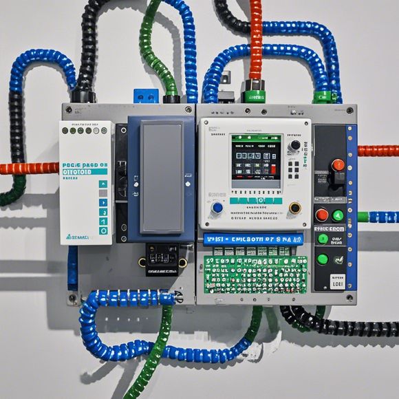
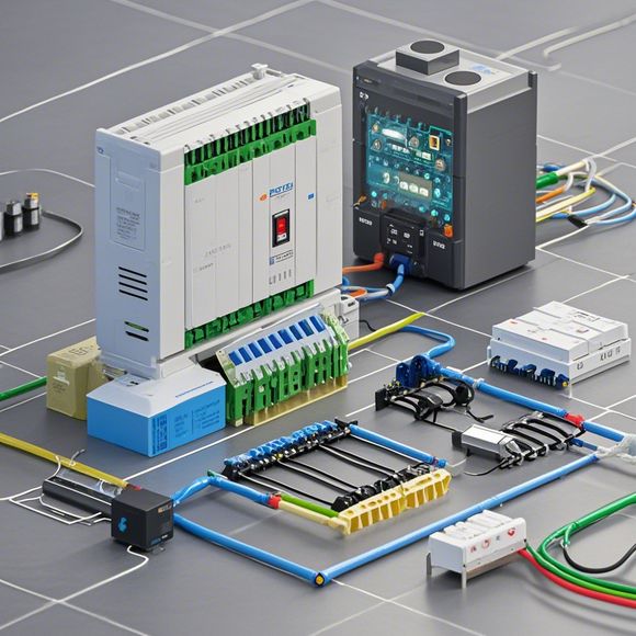
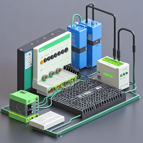
The first thing that strikes us when looking at a PLC is its modular architecture – it's like a Swiss army knife for your factory floor! Each module houses various components such as input/output (I/O) devices, processors, memory, and communication interfaces, all neatly tucked away inside their own compartments. This design not only makes maintenance easier but also promotes fault isolation, enhancing system reliability.
Now, let's talk about wiring diagrams - they serve as the blueprints that guide us through the process of connecting these modules together. These diagrams are often drawn using standard symbols and conventions, making it easy for engineers to understand and follow the connections. They not only help in visualizing the connections but also ensure that no wires are crossed or improperly connected.
But what exactly are these wiring diagrams like? Let’s take a closer look! A typical wiring diagram might start with a schematic layout of the PLC, followed by a detailed list of the I/O ports available on each module along with their respective connections. It includes information about power requirements, signal timing, and other critical details that can make all the difference in ensuring optimal performance.
Moreover, many modern PLC systems come with built-in software that allows you to program the logic directly into the hardware without having to manually connect each wire. This saves time and ensures accuracy, which is particularly useful in high-speed production lines where every second counts.
Now, let's talk about some practical examples of how these wiring diagrams can be applied in real-world scenarios. One common use case is in assembly lines where multiple machines have to communicate with each other. By following a proper wiring diagram, these lines can be set up efficiently and quickly, reducing downtime and increasing overall productivity.
Another important application is in quality control systems where precise measurements need to be made across multiple stations in a production line. Here, wiring diagrams can help identify any potential issues early on, preventing costly rework later on.
Of course, there's more to it than just physical connections. The software within the PLC also plays a crucial role in managing data flow and decision-making. It's like having your own personal assistant, always keeping an eye on things and providing real-time feedback based on inputs from sensors or actuators.
In addition to this, PLCs also come with features like remote monitoring and programming, allowing operators to access and modify settings without physically being present at the factory site. This level of flexibility is truly remarkable!

So, to wrap up our discussion on PLC wiring diagrams and their applications in the modern manufacturing world, it's clear that these tools are more than just mechanical constructs; they are the backbone of our efficient and automated factories. With proper planning and understanding of these diagrams, businesses can achieve unparalleled levels of productivity, efficiency, and profitability. So, next time you're considering investing in new equipment, don't forget to consider the importance of a well-maintained and correctly programmed PLC system!
Content expansion reading:
Content:
Hey there! If you're new to the world of PLCs (Programmable Logic Controllers) or just need a refresher on interpreting those complex wiring diagrams, you've come to the right place. Today, we're diving in and breaking down PLC wiring diagrams with some real-life examples. So, let's get started and demystify those diagrams together!
First things first, what is a PLC wiring diagram? It's a blueprint that shows how all the electrical components in a PLC system are interconnected. This includes the power supply, PLC unit, input devices (like sensors), output devices (like actuators), and any other peripherals. The diagram is crucial for both installation and troubleshooting.
Now, let's talk about what you'll typically see in a PLC wiring diagram. You'll notice symbols for various components, such as:
- Power supply: This is the source of electricity for your PLC system. It's usually a DC or AC power supply unit.
- PLC unit: The heart of the system, where all the logic and decision-making happen.

- Input devices: These could be limit switches, pressure sensors, or any other device that provides data to the PLC.
- Output devices: Actuators like motors, solenoids, or lights that receive commands from the PLC to perform an action.
- Relays and contactors: These are used to control high-current devices.
To make sense of all these symbols, you need to understand the logic behind the diagram. For example, input devices are typically wired to the PLC's input terminals, while output devices are connected to the PLC's output terminals. The PLC then processes the input signals and sends output signals accordingly.
Let's look at a simple PLC wiring diagram:
+
Articles related to the knowledge points of this article:
Mastering the Art of Plc Controllers: A Comprehensive Guide to Understand and Implement
The cost of a PLC Controller: A Comprehensive Analysis
PLC Programming for Automation Control in the Manufacturing Industry
How to Use a PLC Controller for Your Business
Plumbers Rule! The Role of PLC Controllers in the World of Waterworks
The Role of Programmable Logic Controllers (PLCs) in Foreign Trade Operations