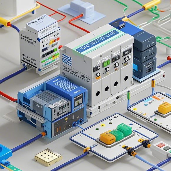
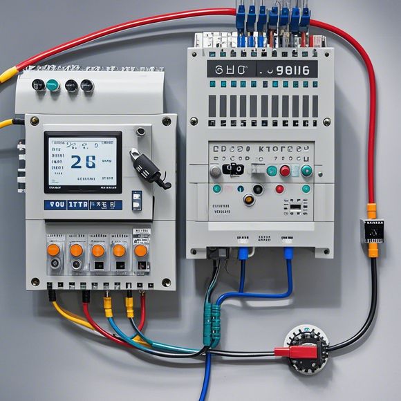
PLC Controller Wiring Diagram
Sure, I can provide a concise summary of the information you have provided based on the PLC Controller Wiring Diagram.**Summary:** The PLC (Programmable Logic Controller) is a device used for industrial automation that allows users to program and control various systems. In this context, the Wiring Diagram refers to the physical layout and connections required for the proper functioning of the PLC. It typically includes diagrams of wire connections, switches, relays, sensors, and other components that interact with the PLC. The wiring diagram helps engineers and technicians understand how different pieces of equipment are connected to form a complete system. This diagram is important for ensuring safe and efficient operation of the industrial processes controlled by the PLC.
Introduction:

As a professional in the field of foreign trade operations, it is essential for me to have a thorough understanding of the various components that make up an industrial control system. One such component is the Programmable Logic Controller (PLC), which plays a crucial role in automating processes and enhancing efficiency within a manufacturing environment. To ensure that I can effectively manage and troubleshoot these systems, I need to have a comprehensive knowledge of their wiring diagrams. In this article, I will explain what an PLC controller wiring diagram is, how to interpret it, and provide some tips for troubleshooting common issues that may arise.
What is an PLC Controller Wiring Diagram?
An PLC controller wiring diagram is an essential document that outlines the connections between the different components of an PLC system. This diagram typically includes information about the input and output devices, the sensors and actuators, and the logic blocks used to control the system. The diagram also provides information on the power supply, communication protocols, and other relevant details. By examining this wiring diagram, one can quickly identify potential issues or areas where modifications may be needed to optimize the system's performance.
Interpreting PLC Controller Wiring Diagrams
When interpreting an PLC controller wiring diagram, it is important to pay attention to the following points:
1、Analyze the connections: Start by carefully examining the diagram to identify the various components that are connected together. Note down the types of wires used, their colors, and any labels indicating specific functions.
2、Determine the logic flow: Look for the logic blocks that control the system's actions. These blocks typically include inputs and outputs, as well as conditional statements that determine when certain events should occur.
3、Identify any errors or warning signs: Pay special attention to any notes or symbols indicating potential errors or warning signs. This can help you quickly identify any issues that may be impacting the system's functionality.
4、Consider external factors: Remember that external factors such as temperature, humidity, and power fluctuations can affect the performance of an PLC system. Make sure to consider these factors in your analysis of the wiring diagram.
Troubleshooting Common Issues with PLC Controller Wiring Diagrams

If you encounter any problems while working with an PLC controller wiring diagram, here are some tips for troubleshooting:
1、Check connections: Ensure that all cables are securely connected to their respective terminals. Double-check that there are no loose connections or damaged cables that could cause interference or failure.
2、Test components: Before making any changes to the wiring diagram, test individual components such as sensors, actuators, and relays to ensure they are functioning properly. This can help you identify any issues with the wiring or components themselves.
3、Use a schematic editor: If you are not comfortable with drawing complex wiring diagrams yourself, consider using a schematic editor to create a detailed representation of the system's connections. This can be particularly helpful if you are working with a team or if you need to review your work with others.
4、Contact support: If you continue to experience issues despite following these troubleshooting steps, contact the manufacturer's support team for assistance. They may be able to provide guidance on how to resolve specific issues or recommend additional tools or resources to help you further troubleshoot the system.
In conclusion, working with PLC controller wiring diagrams is a critical aspect of ensuring that industrial processes are automated and efficient. By understanding how to interpret these diagrams and troubleshooting common issues, you can improve the reliability and effectiveness of your systems. As a foreign trade professional, staying up-to-date with the latest advancements in automation technology is essential for staying competitive in today's global market.
Content expansion reading:
Content:
Hey there! If you're new to the world of PLCs (Programmable Logic Controllers), or you're just looking to brush up on your knowledge, understanding PLC controller wiring diagrams is a crucial step. These diagrams can seem intimidating at first, but once you know what to look for, they're actually pretty straightforward.
So, what exactly is a PLC controller wiring diagram? It's a visual representation of the connections between the various components of a PLC system. This includes the power supply, input devices, output devices, and the PLC itself. The diagram shows you how these components are wired together, which is essential for ensuring that your system is functioning correctly.

When you're looking at a PLC controller wiring diagram, the first thing you'll notice is that it's divided into different sections. The power supply section is usually at the top, followed by the input devices, the PLC, and finally, the output devices. Each section is labeled clearly, so you can easily identify what's what.
Input devices are the sensors that provide data to the PLC. They can be switches, buttons, or more complex devices like temperature sensors or proximity switches. Output devices, on the other hand, are the things that the PLC controls, like motors, lights, or solenoids. The PLC itself is the brain of the system, processing the input data and controlling the output devices accordingly.
The wiring diagram will show you the specific connections between these components. For example, it will show you which input channels are connected to which input devices, and which output channels are connected to which output devices. It will also show you the power connections, both for the PLC and for the devices it controls.
One important thing to look for in a PLC controller wiring diagram is the wiring conventions. Different manufacturers may use different color codes for their wires, so it's important to understand what each color means in the context of the diagram. For instance, red wires are often used for power, while black or blue wires are typically used for control circuits.
When you're working with PLC controller wiring diagrams, it's also important to pay attention to the amperage and voltage ratings of each component. You don't want to connect a high-current device to a circuit that's not rated to handle it. This could lead to damage to the equipment or, in the worst-case scenario, a fire hazard.
If you're ever unsure about a PLC controller wiring diagram, don't hesitate to consult the manufacturer's manual or reach out to a professional. Safety is paramount when working with electrical systems, and a little bit of extra caution can go a long way.
In summary, PLC controller wiring diagrams are a vital tool for understanding how a PLC system is put together. By familiarizing yourself with the different components and the connections between them, you'll be well on your way to becoming a PLC pro. Remember to always approach these diagrams with a critical eye, and if in doubt, seek expert advice.
Articles related to the knowledge points of this article:
Mastering the Art of Plc Controllers: A Comprehensive Guide to Understand and Implement
PLC Controller for Manufacturing Automation
The cost of a PLC Controller: A Comprehensive Analysis
How to Use a PLC Controller for Your Business
PLC (Programmable Logic Controller) Control System Basics
Plumbers Rule! The Role of PLC Controllers in the World of Waterworks