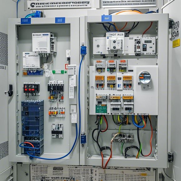
PLC Module Wiring Diagram
The PLC (Programmable Logic Controller) module wiring diagram is a visual representation of how the electrical connections within a PLC system are organized. It includes detailed drawings of the components such as sensors, actuators, and other devices that communicate with the PLC. The wiring diagram also shows the various inputs and outputs that the PLC receives from the various modules and how they are routed to the appropriate outputs or control points. The diagram also includes details of the power supply, grounding, and any safety features such as fuses or circuit breakers. Overall, the PLC module wiring diagram is crucial for understanding the internal architecture of a PLC system and ensuring that it can be safely operated and maintained.
Hello, my name is [Your Name], and I'm here to guide you through the process of wiring a PLC module in your manufacturing system. Let's dive into this topic together.
Firstly, let's start by discussing what a PLC (Programmable Logic Controller) is. It stands for Programmable Logic Controller, which is essentially a computer system that can be programmed to perform various tasks. It's used in industrial automation systems, where it controls the flow of materials and processes in manufacturing plants.

Now, onto the topic at hand - the PLC module wiring diagram. This is a visual representation of how the various components in your system are connected to each other. Here's what we'll cover:
1、Identifying the Parts: The first step is to identify all the components in your system, including the PLC itself, switches, sensors, actuators, etc. This will help us understand the overall structure and functionality of your system.
2、Drawing the Diagram: Once we have identified all the parts, we can start drawing the wiring diagram. This should include all the connections between the different components, as well as any necessary labels or notes.
3、Connecting the Components: Next, we need to connect the different components together according to their requirements. For example, if you have a switch that needs to control a motor, you would connect it to the PLC input pins. Similarly, if you have sensors that need to send data back to the PLC, you would connect them to the output pins.
4、Testing the System: Once everything is connected, it's important to test the system to ensure that it works as expected. You might want to run some simple scripts or programs to see if they work properly, and also check that the signals from the sensors and actuators are being received correctly.
5、Documentation: Finally, it's important to document everything you've done. This includes writing down all the connections and any notes you made during the testing process. It's also a good idea to keep a copy of the diagram for yourself in case something goes wrong later on.
So there you have it - a step-by-step guide to wiring a PLC module in your manufacturing system. If you have any questions or need further assistance, feel free to ask me.
Content expansion reading:
Content:
Hey there, fellow tech enthusiasts! Today, we're diving into the world of PLCs, or Programmable Logic Controllers. These bad boys are the brains of many industrial control systems, and understanding their module wiring diagrams is crucial for keeping everything running smoothly. So, let's get started on demystifying these diagrams!

First things first, a PLC module wiring diagram is a blueprint that shows how different components of a PLC system are electrically connected. It's like a roadmap that tells you where each wire should go and what each connection means. Without it, you'd be lost in a sea of wires with no direction.
Now, these diagrams can look a bit intimidating with all those lines and symbols, but fear not! Each symbol represents a specific component or action, such as inputs, outputs, relays, and more. Once you learn the language of these diagrams, it's like unlocking a secret code.
One of the key components you'll see in a PLC module wiring diagram is the input. These are the signals that the PLC receives from sensors or switches. They can be digital (on/off) or analog (varying voltage or current). Inputs are represented by symbols that look like switches or waves, depending on their type.
Outputs, on the other hand, are the signals that the PLC sends to actuators like motors or lights. Again, these can be digital or analog. In the diagram, you'll see output symbols that look like the devices they control or like arrows indicating the flow of energy.
Relays are another common feature in PLC modules. They're like switches that can be controlled by the PLC. The wiring diagram will show how the PLC connects to the relay and how the relay connects to other devices.
Now, let's talk about power. The diagram will show the power supply connections, both for the PLC itself and for any devices it controls. This is where you'll see the + and - symbols indicating the flow of electrical current.
When you're looking at a PLC module wiring diagram, it's important to pay attention to the labels and numbers on the wires. These indicate the specific function of each wire and help you ensure that everything is connected correctly.
In summary, PLC module wiring diagrams might seem complex at first, but they're just a way to communicate the connections between components. Once you know what the symbols mean and how to interpret the labels, you'll be able to troubleshoot issues, make repairs, and even expand your system with ease. So, grab a diagram and start exploring – the world of PLCs is waiting for you to unravel its mysteries!
Articles related to the knowledge points of this article:
PLC Controller Selection Guide for Foreign Trade Operations
How to Use a PLC Controller for Your Business
PLC (Programmable Logic Controller) Control System Basics
Connecting a PLC Controller to Your Computer
PLC Controllers: A Comprehensive Guide to Understanding Their Prices