PLC Input Output Interface Design and Application
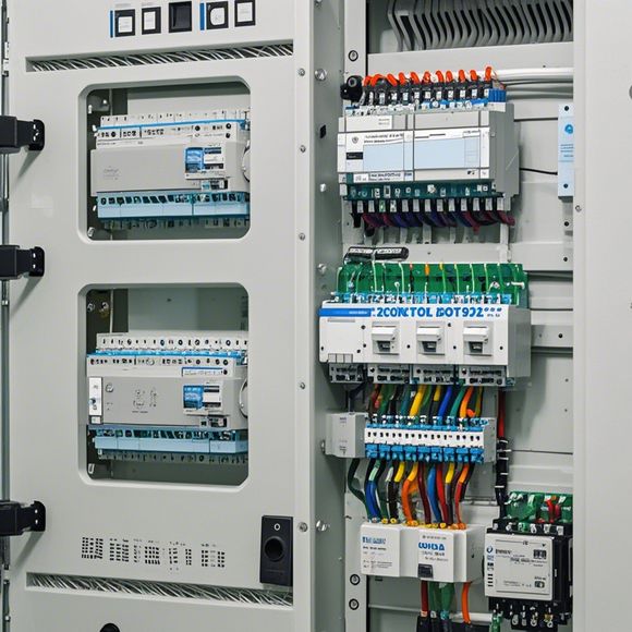
The PLC (Programmable Logic Controller) input output interface is a crucial component in the design of industrial automation systems. Its primary function is to enable communication between the control system and various sensors, actuators, and other equipment. This design involves selecting appropriate components such as sensors, actuators, and interface circuitry, which are then connected in a specific configuration to meet the system requirements.The application of PLC input/output interfaces is widespread across various industries including manufacturing, healthcare, transportation, and energy. In manufacturing, for example, they are used to control machines and equipment based on real-time data from sensors. In healthcare, they are used to monitor patient conditions and adjust treatments accordingly. In transportation, they are used to control traffic lights and highway signals. In energy, they are used to manage power grids and ensure safe operations.Overall, the PLC input/output interface plays a critical role in ensuring efficient and reliable operation of industrial automation systems. By carefully designing these interfaces, we can achieve greater control over complex processes and improve overall productivity and safety.
Introduction to PLC Input Output System:

The PLC (Programmable Logic Controller) is a key component in modern industrial automation systems. It allows for precise control over various processes through the use of digital input/output signals. The PLC's ability to process and analyze these inputs allows it to execute specific commands and generate output signals, thus enabling automation of complex industrial operations.
Designing an Effective PLC Input Output System:
Designing a successful PLC input/output system requires careful planning and consideration of various factors. Firstly, it is important to identify the functions required by the system and determine which inputs and outputs are necessary to achieve those functions. This will help in selecting the appropriate hardware components and programming logic accordingly.
Choosing Hardware Components:
When selecting hardware components for the PLC input/output system, it is essential to consider factors such as reliability, compatibility, and ease of integration. Some commonly used hardware components include sensors, actuators, switches, and motors. These components can be connected to the PLC via appropriate interfaces such as RS-232, I2T, or I2C, depending on the type of hardware being used.
Programming Logic for Input/Output Signals:
Once hardware components have been selected, the next step is to program the PLC with the necessary logic for processing the input signals and generating output signals. The programming language used depends on the specific PLC model being used. For example, some PLCs may require the use of ladder logic diagrams while others may require block diagrams or function blocks.
Monitoring and Testing the PLC Input Output System:
After programming, it is crucial to monitor the system's functionality and test it thoroughly to ensure that it is working correctly. This includes testing different scenarios and scenarios under different conditions to verify that the PLC system is reliable and efficient.
Conclusion:
In conclusion, designing an effective PLC input/output system requires careful planning, consideration of various factors, and proper implementation. By choosing the right hardware components and programming the PLC with appropriate logic, one can create a robust and efficient system that can handle various industrial applications.

Content expansion reading:
Content:
Hey there! If you're new to the world of PLCs (Programmable Logic Controllers), one of the first things you'll need to wrap your head around is how to interpret those complex input and output wiring diagrams. Don't worry, though—it's not as daunting as it seems! Let's break it down in a way that's easy to understand.
First things first, what is a PLC? It's a type of industrial computer that's designed to control and automate various types of machinery and processes. The heart of a PLC is its I/O (Input/Output) system, which is what we're going to focus on today.
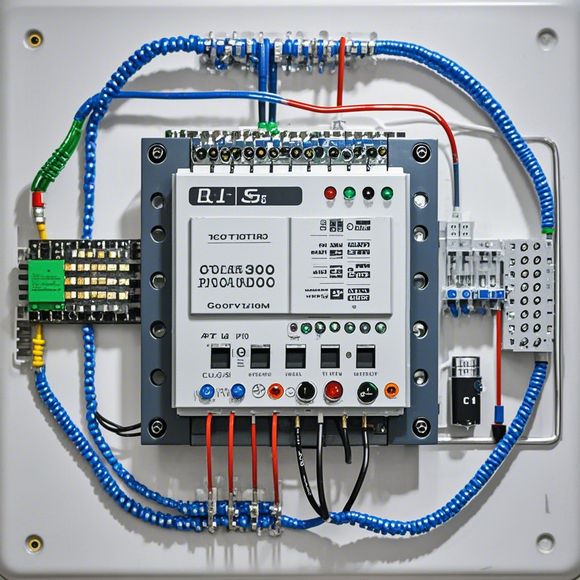
An I/O wiring diagram is a blueprint that shows how the PLC is connected to the devices it controls or monitors. Inputs are the signals that the PLC receives from sensors, switches, or other devices, telling it what's happening in the system. Outputs, on the other hand, are the signals the PLC sends to actuators, motors, or lights to control the system.
When you're looking at a PLC I/O wiring diagram, you'll typically see a grid or a list of inputs and outputs, each with a specific function and address. The inputs are usually on the left, and the outputs are on the right. Each input or output is represented by a letter or a number, and they're arranged in a specific order.
Let's talk about inputs. These are the things that the PLC "sees" and reacts to. Common types of inputs include:
- NC (Normally Closed) contacts: These are closed when the switch is off.
- NO (Normally Open) contacts: These are open when the switch is off.
- PNP (Positive-Negative-Positive) sensors: These are active when the voltage at the output is higher than the voltage at the input.
- NPN (Negative-Positive-Negative) sensors: These are active when the voltage at the input is lower than the voltage at the output.

Outputs, on the other hand, are what the PLC "does" in response to the inputs. They can be:
- Relay outputs: These are mechanical switches that control high-current devices.
- Solid-state outputs: These are semiconductor devices that can switch on and off very quickly.
- Analog outputs: These provide a continuous signal that can vary in value.
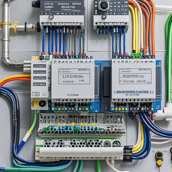
To connect an input or output to the PLC, you'll need to use the correct wiring. The wiring diagram will show you the pin numbers and colors you need to use. Make sure you follow the wiring diagram carefully to avoid any mistakes.
Now, let's talk about symbols. PLC diagrams use a set of standard symbols to represent different types of inputs and outputs. For example, a switch might be represented by a rectangle with two lines inside, while a sensor might be represented by a circle with a line inside.
When you're working with PLCs, it's important to understand the function of each input and output, as well as the logic behind the program that the PLC is running. This will help you troubleshoot any issues that might arise and ensure that your system is running smoothly.
Remember, safety is paramount when working with PLCs and electrical systems. Always follow proper safety procedures, including wearing the appropriate personal protective equipment (PPE) and ensuring that the power is off before making any connections.
That's it for a quick overview of PLC input and output wiring diagrams. Understanding these diagrams is a crucial step in maintaining and troubleshooting PLC-controlled systems. So, grab a diagram, a multimeter, and your favorite tool belt, and get ready to dive into the world of automation!
Articles related to the knowledge points of this article:
PLC Controller for Manufacturing Automation
The cost of a PLC Controller: A Comprehensive Analysis
PLC Programming for Automation Control in the Manufacturing Industry
PLC (Programmable Logic Controller) Control System Basics
Connecting a PLC Controller to Your Computer
PLC Controllers: A Comprehensive Guide to Understanding Their Prices