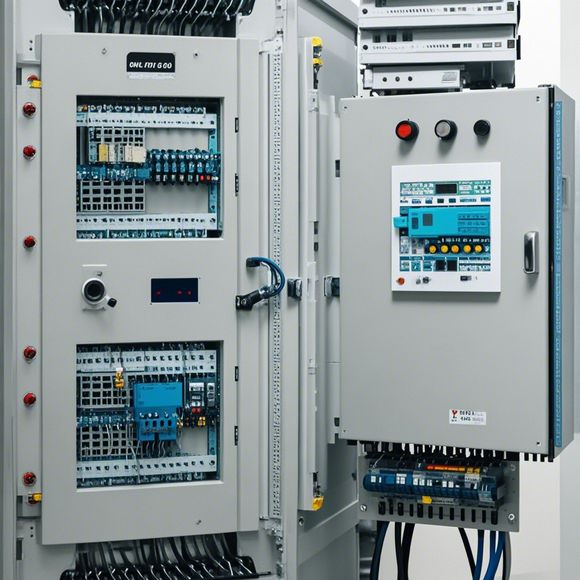
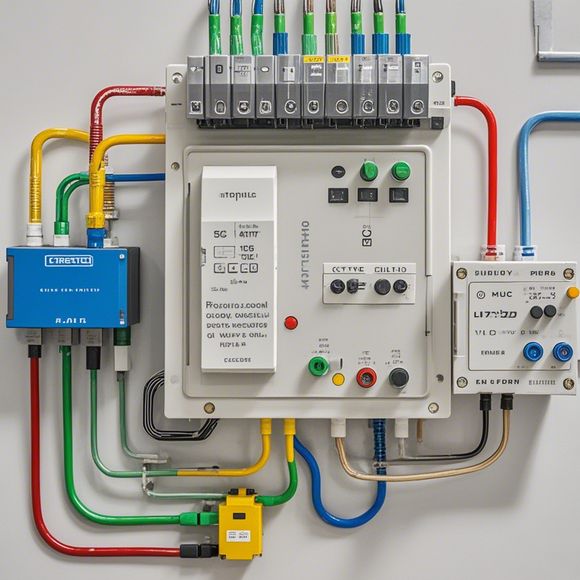
A Comprehensive Guide to PLC Control Cabinet Wiring Diagrams
Sure, here's a summary of the content you provided in 200-300 words:PLC Control Cabinet Wiring Diagrams,A Comprehensive Guide to PLC Control Cabinet Wiring DiagramsPLC (Programmable Logic Controller) control cabinets are widely used in industrial applications for controlling various machines and processes. To ensure that these systems function properly, wiring diagrams play a crucial role in showing the electrical connections between different components within the control cabinet.In this guide, we will provide an overview of the key elements that should be included in a typical PLC control cabinet wiring diagram. The diagram should clearly indicate the location of each circuit, the type of connection used, and any special requirements for power or signal levels. Additionally, it is important to include detailed notes on the installation process, testing procedures, and any safety measures necessary for proper operation and maintenance of the PLC control cabinet system.By following these steps and guidelines, you can effectively design and implement a reliable and efficient PLC control cabinet system that meets the needs of your industrial application.
In today's world, where automation and control technologies play a significant role in various industries, understanding the intricacies of PLC (Programmable Logic Controller) control cabinet wiring is crucial. A well-structured wiring diagram not only helps in troubleshooting issues but also ensures smooth operation of the entire system. Therefore, it's essential that one has an up-to-date guide on how to read and follow such diagrams. This comprehensive guide will walk you through each step involved in creating a PLC control cabinet wiring diagram, from the initial layout to final configuration. Whether you're a novice or an experienced technician, this resource will provide valuable insights into achieving a successful installation. So let's dive deep into the world of PLC wiring and discover the secrets behind ensuring a reliable and efficient system.
Firstly, it's important to understand the basic components of a PLC control cabinet, which typically include the CPU, input/output modules, communication modules, sensors, actuators, and other peripherals. Each component plays a critical role in the system's functionality, and their correct connection is crucial for achieving optimal results. To create a functional wiring diagram, one must first identify the electrical requirements of each component, including its power sources and signal inputs/outputs. This involves carefully analyzing the component's specifications and determining the appropriate wire type, voltage, and current required for each connection. Once these requirements are established, one can proceed to draw the wiring diagram by using tools such as multimeters, oscilloscopes, or software programs designed specifically for PLC wiring.

The process of creating a wiring diagram involves several steps. Firstly, start by drawing all the components of the control system, including the CPU and each module, along with their connections to the power source and other components. It's essential to ensure that each component is accurately positioned and labeled, making it easy to locate and troubleshoot any issues later on. Next, connect each component to the appropriate terminal block or switch according to the wiring diagram. It's recommended to use color coding or other visual cues to distinguish different types of connections, such as grounding, power supply, data lines, and control signals. Additionally, it's important to pay attention to the placement and orientation of the wiring cables, as incorrect connections can lead to potential safety risks or performance issues.
After completing the wiring diagram, it's essential to review it for accuracy and completeness. One should check for any missing connections, double check the placement of components, and verify that all connections meet the required standards. It's also important to test the system before finalizing the wiring diagram, to ensure that all components are functioning correctly and that there are no short circuits or other errors. If any issues are found during testing, they should be addressed immediately before finalizing the wiring diagram. By following these steps, one can successfully create a functional and efficient PLC control cabinet wiring diagram, ensuring optimal operation of the entire system.
In conclusion, understanding and implementing a comprehensive guide on how to read and follow PLC control cabinet wiring diagrams is crucial for any professional involved in the field. This guide provides valuable insights into the basic components involved in creating a functional wiring diagram, from identifying electrical requirements to testing and finalizing the system. By following these steps, one can achieve a successful installation and ensure optimal operation of the system. Remember, proper wiring is key to achieving reliable and efficient control systems, so take the time to learn and implement this knowledge effectively.

Content expansion reading:
Articles related to the knowledge points of this article:
PLC Programming for Automation Control in the Manufacturing Industry
How to Use a PLC Controller for Your Business
PLC (Programmable Logic Controller) Control System Basics
PLC Controllers: A Comprehensive Guide to Understanding Their Prices
Effective Strategies for Handling PLC Control System Faults
PLC Controller Advantages: A Comprehensive Guide for Success in Global Trade