PLC Wire Diagram & Physical Map
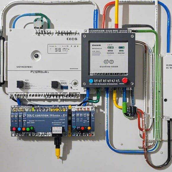
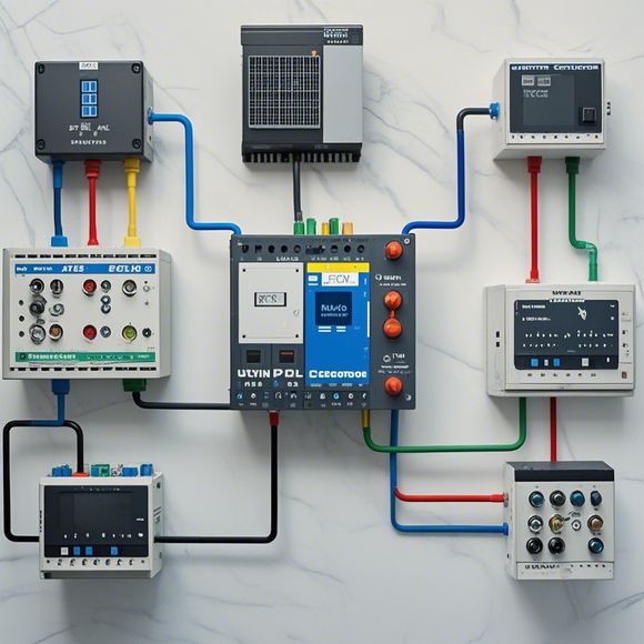
In the realm of electrical engineering, the PLC (Programmable Logic Controller) plays a vital role in the automation of industrial processes. A PLC wire diagram and physical map are two essential tools used to design and understand the internal workings of these controllers.A wire diagram is a visual representation of the electrical connections within a PLC system. It includes detailed diagrams that show how different components are wired together, including sensors, actuators, and processors. This diagram helps engineers quickly identify and troubleshoot issues when there's an issue with the system.On the other hand, a physical map shows the layout of the PLC cabinet or its location within the control room. It also includes information about the various components inside the cabinet, such as switches, relays, and input/output ports. This map is crucial for ensuring that all components are correctly positioned and connected to their respective inputs and outputs.Overall, understanding the wire diagram and physical map is critical for anyone who works with PLC systems, as it allows them to quickly diagnose and fix problems without needing to physically inspect the device.
As an experienced foreign trade operator, I have been tasked with ensuring the smooth operation of a manufacturing line. In order to achieve this goal, it is crucial for us to understand the intricacies of the process and ensure that everything runs smoothly. This includes understanding how the production line is connected to the different machines and equipment, as well as how the data flows between the different components.
To accomplish this, we need to refer to the plc (programmable logic controller) circuit diagram. This is a detailed representation of the electrical connections between the various components of the system. By examining the diagram, we can identify the specific wires and terminals required for each component, as well as the appropriate voltage levels and signal frequencies. This information is essential in ensuring that the system operates efficiently and reliably.
Once we have obtained a clear understanding of the circuit diagram, we can proceed to examine the physical map of the system. This is a visual representation of the actual components within the system. By comparing the diagram with the physical map, we can identify any discrepancies or errors in our initial assessment of the system. It also allows us to identify any potential issues with the electrical wiring or connectors used in the system.
In addition to this, we must also pay close attention to any signs of wear and tear on the wiring or connectors. This could indicate that the system is overloaded or has been exposed to excessive vibration or temperature changes, which can cause damage to the components over time. It is important to address these issues promptly to prevent further complications and ensure the longevity of the production line.

Overall, by carefully examining both the plc circuit diagram and the physical map of the manufacturing system, we can gain a deeper understanding of how the different components work together to produce a successful product. This knowledge will enable us to identify any potential problems early on and take action to address them before they become more serious issues. With careful planning and attention to detail, we can ensure that our manufacturing line runs smoothly and efficiently, meeting the highest standards of quality and reliability.
Content expansion reading:
Content:
Hey there! If you're new to the world of PLCs (Programmable Logic Controllers) or just need a refresher on interpreting those complex wiring diagrams, you've come to the right place. Today, we're diving into the nitty-gritty of PLCs with a focus on deciphering those confusing diagrams by looking at real-life examples. So, grab a cup of coffee, and let's get started!
First things first, what is a PLC wiring diagram? It's a blueprint that shows how all the electrical components of a PLC system are interconnected. This includes the power supply, PLC unit, input devices (like sensors), output devices (like actuators), and any other peripherals. The diagram is essential for troubleshooting, maintenance, and understanding how the system works.
Now, let's talk about why these diagrams can be so confusing. For starters, they often use a variety of symbols to represent different components, and if you're not familiar with these symbols, the diagram might as well be written in a foreign language. Additionally, the sheer number of wires and connections can be overwhelming, especially for beginners.
But don't worry, we're going to demystify all of this together. To make things easier, I've got a couple of real-world PLC wiring diagrams here that we're going to break down step by step. By the end of this, you'll be able to look at a PLC wiring diagram and understand exactly what's going on.
First diagram we're going to look at is a relatively simple one for a small automation system. Here's what you should focus on when analyzing a diagram like this:
1、Power Supply: This is where the electrical power comes from to run the entire system. You'll usually see a symbol for a power supply with a plus and minus sign.

2、PLC Unit: This is the brain of the operation. It's where all the logic and decision-making happen. Look for a rectangular box with various ports on it.
3、Input Devices: These are the sensors that provide data to the PLC. They're represented by switches, buttons, or other symbols depending on the type of sensor.
4、Output Devices: These are the actuators that do the work based on the PLC's instructions. They might be motors, lights, or anything else that needs to be controlled.
5、Wires and Connections: These are the most confusing part for many people. Each wire is labeled with a specific function, and the connections between components are critical.
Let's go through the diagram and identify each of these elements. Once you've got the hang of it, we'll move on to a slightly more complex diagram to see if you can apply what you've learned.
Remember, the key to understanding PLC wiring diagrams is practice. The more you look at them, the easier they'll become to interpret. If you get stuck, don't hesitate to reach out to a more experienced colleague or refer to the manufacturer's manual for guidance.
Alright, that's it for today. I hope this has been helpful in demystifying PLC wiring diagrams. If you have any questions or need further assistance, feel free to reach out. Happy troubleshooting!
Articles related to the knowledge points of this article:
PLC Programming for Automation Control in the Manufacturing Industry
How to Use a PLC Controller for Your Business
Plumbers Rule! The Role of PLC Controllers in the World of Waterworks
The Role of Programmable Logic Controllers (PLCs) in Foreign Trade Operations
PLC Controllers: A Comprehensive Guide to Understanding Their Prices