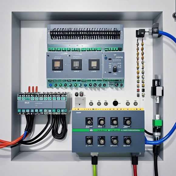
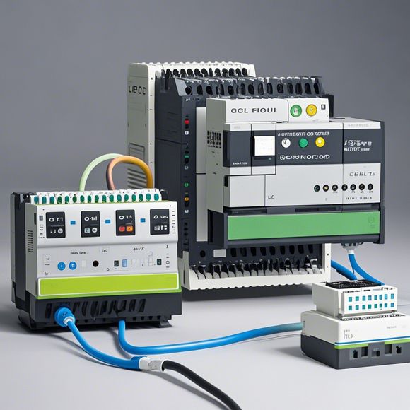
plc输入输出接线图
根据您提供的内容,下面我将为您生成一段200-300个字的口语化英文摘要:The Plc Input/Output wiring diagram is a crucial component in the operation of Programmable Logic Controllers (PLCs). The process begins with the connection of external input signals, which are then processed by an input relay in the Plc. These input relays can offer multiple output contacts to support the programming needs of the PLC content control circuitry. The function of the PLC output circuit is to convert the processed input signals into the appropriate output actions, such as turning on or off devices or controlling motor speeds.This process involves understanding the common inputs and outputs for different brands of PLCs, as well as their respective signal differences. It's also beneficial to have some handy tips or abbreviations that make it easier to remember and apply the wiring methods.In summary, understanding the PLC input/output wiring diagram is essential for ensuring efficient and reliable operation of industrial automation systems. By mastering the connections between input and output components, engineers can effectively control complex processes and enhance productivity.
"Mastering the Art of PLC Programming and Debugging: A Practical Guide for Successful Automation Projects"
Introduction:

Welcome to the world of programmable logic controllers (PLCs), the backbone of industrial automation. Whether you're a seasoned technician or a novice looking to get your feet wet, this guide is designed to arm you with the knowledge and skills necessary to navigate the complex landscape of PLC programming and troubleshooting. From understanding the basics to mastering advanced features, we'll cover everything you need to know to become a pro at PLC programming.
Step-by-Step Guide to PLC Programming:
1、Understanding the Basics: Before diving into the technical aspects of PLC programming, it's essential to understand the fundamentals. This includes learning how to read and interpret PLC input and output signals, as well as the various types of sensors, actuators, and control algorithms that are commonly used in industrial applications.
2、Choosing the Right PLC: Selecting the right PLC for your project is crucial. Consider factors such as processing power, memory capacity, communication protocol compatibility, and cost when making your decision. It's also important to choose a PLC that meets the specific needs of your application, whether it's for simple tasks or complex systems.
3、Setting Up the PLC Environment: Once you have your PLC, it's time to set up the environment for programming. This includes configuring the PLC's hardware settings, such as selecting the correct pin numbers for input and output devices. You may also need to create a software environment, such as installing a development suite or using a high-level language (HLL) for programming.
4、Learning the Language and Toolkits: The next step is to learn the language and toolkits used for PLC programming. There are several popular languages and toolkits available, each with their strengths and weaknesses. Some popular options include Ladder Logic, Function Block Diagrams (FBD), Sequential Function Charts (SFC), etc. Choose the language and toolkit that best suits your needs and familiarity with programming concepts.
5、Writing the Code: With the PLC environment set up and the programming tools installed, the actual coding begins. Start by writing simple programs to test your understanding of the language and toolkit. As you gain more experience, move on to complex projects and tackle real-world problems with more intricate code. Remember to adhere to best practices for code organization, commenting, and error handling.
6、Debugging and Testing: One of the biggest challenges in PLC programming is debugging and testing. Use tools like PLC Simulation, Programmable Logic Controller Simulator, and Real-time Simulation Tools to simulate the system before implementing the program in the real PLC. Test different scenarios to ensure that the program works as expected and can handle unexpected inputs or conditions.
7、Monitoring and Maintenance: Finally, after completing the programming and testing phase, it's time to monitor and maintain the PLC system. Set up alarms and notifications to detect any issues or changes in the system. Conduct routine maintenance checks, including cleaning and replacing parts, to prevent failures and extend the lifespan of the PLC.
Advanced Tips for Mastering PLC Programming:
1、Stay Up-to-Date: The world of PLC programming is rapidly evolving, so it's crucial to stay informed about new technologies and trends. Attend training sessions, subscribe to industry publications, and network with other professionals in your field to stay ahead of the curve.
2、Practice Makes Perfect: Like any skill, mastering PLC programming requires practice. Set aside dedicated time each week to work on projects, either alone or with a team. Practice makes perfect, so don't be afraid to fail and learn from your mistakes.
3、Communicate Clearly: When working with others on a PLC project, clear communication is key. Be sure to explain the purpose, design, and logic behind each component in your program. Use diagrams, flowcharts, and comments to help others understand your ideas and avoid misunderstandings.
4、Seek Help When Needed: Don't hesitate to reach out to colleagues, friends, or mentors if you encounter difficulties or questions along the way. They may have valuable insights or solutions that can help you overcome obstacles and continue progressing towards success.
In conclusion, becoming a master of PLC programming and troubleshooting takes dedication, hard work, and a willingness to learn. By following the steps outlined above, you can arm yourself with the knowledge and skills necessary to tackle any PLC project head-on and achieve success in your automation endeavors. So go ahead, grab your favorite cup of coffee, and let's embark on this exciting journey together!
Content expansion reading:
Content:

Hey there! If you're new to the world of PLCs (Programmable Logic Controllers), one of the first things you'll need to wrap your head around is how to interpret those complex input and output wiring diagrams. Don't worry, though—it's not as daunting as it seems! Let's break it down in a way that's easy to understand.
First things first, what is a PLC? It's a type of industrial computer that's designed to control and automate various electromechanical processes. These processes can range from simple on/off control to complex data handling and motion control.
Now, let's talk about input and output devices. Input devices are the eyes and ears of the PLC, allowing it to "see" what's happening in the real world. Common inputs include switches, sensors, and timers. Output devices, on the other hand, are the hands and feet—they do the actual work, controlling things like motors, lights, and valves.
A PLC input output wiring diagram is a blueprint that shows how these devices are connected to the PLC. It's a visual representation of the electrical circuit, and it's crucial for ensuring that your system is wired up correctly.
Here's a simple guide to help you understand what you're looking at in a typical PLC input output diagram:
1、PLC Channels: These are the points where the PLC "talks" to the outside world. Each channel is assigned a specific function, like controlling a motor or monitoring a temperature sensor.
2、Inputs: These are represented by circles or squares, and they show how the PLC is connected to the devices that provide it with information. For example, a switch might be wired to an input channel, and when the switch is flipped, the PLC receives a signal.
3、Outputs: These are represented by squares or rectangles, and they show how the PLC communicates with devices to control them. When the PLC decides to turn on a motor, it sends a signal through an output channel to make it happen.
4、Labels: Every input and output should be clearly labeled with its function or device type. This could be something like "Emergency Stop Switch" or "Motor Control."
5、Wiring: The actual wires in the diagram connect the inputs and outputs to their respective devices. Make sure the wiring matches the diagram exactly to avoid any issues.
6、Power Supply: Don't forget about the power! The diagram should show how the PLC is connected to the main power source, as well as any secondary power supplies for different parts of the system.
7、Grounding: Proper grounding is essential for safety and to prevent electrical noise. Look for ground symbols in the diagram to ensure they're connected correctly.
Remember, the key to understanding a PLC input output wiring diagram is to take it step by step. Start by identifying the different components, then look at how they're connected, and finally, make sure you understand what each part does.
If you're ever in doubt, don't hesitate to reach out to a more experienced colleague or consult the manufacturer's documentation. Safety and proper function are paramount when dealing with PLCs and electrical systems.
So there you have it—a quick and easy guide to help you navigate those PLC input output wiring diagrams. With a bit of practice, you'll be reading them like a pro in no time!
Articles related to the knowledge points of this article:
Smart Manufacturing Solutions with PLC Integrated Machinery
The cost of a PLC Controller: A Comprehensive Analysis
How to Use a PLC Controller for Your Business
The Role of Programmable Logic Controllers (PLCs) in Foreign Trade Operations
PLC Controllers: A Comprehensive Guide to Understanding Their Prices