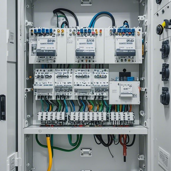
PLC Input/Output Wiring Diagram for Your Trade
Sure, here's a brief summary of the content in 200-300 word format:In your industry, you're responsible for managing the flow of information between your computer system and external hardware devices. To achieve this, you need a PLC (Programmable Logic Controller) input/output wiring diagram. This diagram will help you understand how to connect different components to your computer and communicate with the external devices.Firstly, it's essential to determine the number and types of sensors and actuators that need to be connected to your computer. You should also consider their locations and how they interact with each other. Once you have identified all the relevant components, you can start drawing the wiring diagram using a software tool like Eagle or KiCad.The diagram should include details such as pin connections, voltage levels, power requirements, and data transmission protocols. It's crucial to make sure that all the connections are properly labeled and labeled according to the manufacturer's specifications.Finally, test the wiring diagram thoroughly before implementing it in your system. This step is essential for ensuring that all components are correctly connected and working together.By following these steps, you can create a reliable PLC input/output wiring diagram that helps you maintain a smooth workflow within your industry.
Hello, dear friends and partners! Today, I'm thrilled to share with you an invaluable resource that is sure to help you navigate the world of international trade. It's all about PLC (Programmable Logic Controller) input/output (IO) wiring diagrams. These diagrams are like the roadmaps that guide us to success in our business ventures. They provide a clear understanding of how different components of your system communicate with each other, ensuring seamless operation and efficiency throughout your operations.

So, without further ado, let's take a look at some common features that are present in these diagrams:
1、Device Connection: This represents the physical connection between various devices in your plant, such as sensors, motors, switches, and actuators. Each device has its own unique pin number, which is essential for accurate wiring.
2、Function Blocks: These are placeholders where you can define the functions that your PLC will execute based on the inputs from the device connections. For example, if you have a temperature sensor connected to your PLC, you might have a function block for temperature control or analysis.
3、Inputs: This is where you specify the signals that the PLC receives from various external sources. For instance, if you have a pressure sensor, it would be connected to the PLC with an input line marked 'Pressure'.
4、Outputs: These represent the signals that the PLC sends to various external devices. For example, if you have a motor controller connected to the PLC, it would be connected with an output line marked 'Motor'.
5、Alarm System: This feature is designed to alert you when something goes wrong. You can set up alarms for various conditions such as overheating, low battery, or faulty connections.

6、Programming Language: Some PLC manufacturers offer programming languages that allow you to write code directly into your PLC to control specific functions. For example, you might use a language like Ladder Logic (LL), Function Block Diagram (FBD), or Sequential Function Chart (SFC).
7、Error Handling: This feature allows you to handle errors that may arise during the operation of your PLC system. You can designate specific error codes and their corresponding responses, ensuring smooth operation even in case of unexpected situations.
8、Security Features: Some PLC systems come with additional security options like encryption, password protection, and remote access. These features are crucial for maintaining the integrity and security of sensitive data and processes.
Now, let's talk about how you can use these PLC input/output wiring diagrams in your business:
Plan Ahead: Before starting any project, it's essential to plan ahead and draw the PLC input/output wiring diagrams accurately. This helps in avoiding costly mistakes and delays later on.
Train the Team: Once you have your diagrams ready, make sure everyone involved in the project understands them thoroughly. Proper training can save you time and money in the long run.

Monitor Performance: Use real-time data monitoring tools to track the performance of your PLC system. This way, you can identify any issues early on and resolve them before they become major problems.
Regular Maintenance: Schedule regular maintenance checks for your PLC system. This includes cleaning the circuit boards, checking for dust accumulation, and testing the connections for proper functionality.
In conclusion, PLC input/output wiring diagrams play a critical role in optimizing your trade operations. By following the tips mentioned above, you can ensure that your system runs smoothly and efficiently. Remember, investing in good quality wiring and proper training can lead to significant cost savings in the long term. So go ahead and get your hands on those PLC input/output wiring diagrams today and start reaping the benefits for yourself and your company!
Content expansion reading:
Articles related to the knowledge points of this article:
PLC Controller for Manufacturing Automation
The cost of a PLC Controller: A Comprehensive Analysis
PLC Programming for Automation Control in the Manufacturing Industry
PLC (Programmable Logic Controller) Control System Basics
Plumbers Rule! The Role of PLC Controllers in the World of Waterworks