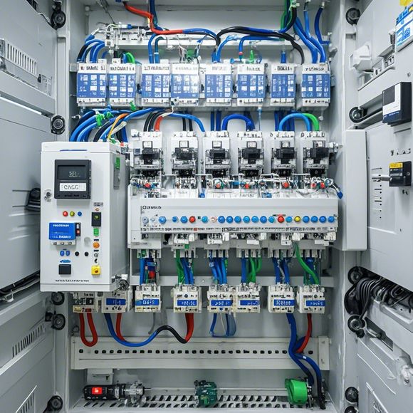
PLC Controller Wiring Diagram
Certainly, here is a summary of the content you provided in English:PLC (Programmable Logic Controller) Controller Wiring DiagramIn the world of industrial automation, the PLC controller plays an important role. This diagram shows the basic wiring connections for a typical PLC controller.The first connection on the top left is the power supply, which connects to a wall outlet or battery pack. This provides the necessary electricity needed by the PLC controller.The next connection is the Ethernet cable, which connects the PLC controller to a computer or other device. This enables communication between the two devices and allows for programming and data monitoring.The third connection is the input/output (I/O) interface. This allows for the connection of sensors, switches, and other devices that provide data to the PLC controller.The fourth connection is the display screen, which displays information from the PLC controller such as program status, error messages, and data outputs.Overall, a PLC controller wiring diagram is important for understanding how the components work together to control and monitor various industrial processes.
Hello everyone,
Today, I would like to talk about the importance of a plc (programmable logic controller) controller wiring diagram. A well-written and detailed wiring diagram is crucial for ensuring that the system functions smoothly and effectively. In this discussion, we will explore the various elements that make up a plc controller and how they work together to control and monitor the system.

First, let's take a look at the basic components of a plc controller. These include:
1、CPU (Central Processing Unit): The CPU is the brain of the plc controller. It performs all the calculations required to control the system and manage the data flow between different modules. The CPU is responsible for interpreting input signals and generating output signals based on predefined rules.
2、RAM (Random Access Memory): RAM stores the program code for the plc controller, which enables it to execute instructions and perform operations. The amount of RAM available can vary depending on the complexity of the system being controlled.
3、ROM (Read-Only Memory): ROM stores the initial program code for the plc controller, which is read during startup but cannot be changed or updated afterward. ROM is used to store the operating system and other critical software components.
4、Power Module: The power module provides the necessary electrical connections to connect the components of the plc controller to the electrical system. It ensures that the correct voltage and current levels are supplied to each component.

5、Input Module: The input module collects and processes input signals from external sources such as sensors, switches, and actuators. It converts these signals into digital format that can be processed by the CPU.
6、Output Module: The output module generates and controls the signals required to control the external devices connected to the plc controller. This includes motors, valves, and other actuators.
Now, let's move on to some common wiring practices when connecting these components together. Here are some important considerations:
1、Use appropriate cable types: Different wires have different characteristics, such as resistance, capacitance, and insulation resistance. Using the right type of cable for each connection is crucial for maintaining proper signal integrity and preventing interference.
2、Ensure good grounding: Good grounding is essential for ensuring safety and stability in the system. Grounding helps to minimize electromagnetic interference and protect against electrostatic discharges.

3、Use appropriate terminal blocks: Terminal blocks are used to connect cables to the plc controller. They should be selected according to the type of cable being used and the specifications of the device.
4、Test connections frequently: After making any connections, it is important to test them periodically using a multimeter or similar device to ensure that there are no short circuits or open connections.
In conclusion, a well-written plc controller wiring diagram is an essential tool for ensuring that the system functions correctly and efficiently. By following the above tips, you can ensure that your connections are reliable and effective, allowing you to optimize performance and minimize downtime. Remember to consult with a qualified professional if you need help with complex wiring projects, as incorrect connections can lead to costly repairs or even safety hazards.
Content expansion reading:
Articles related to the knowledge points of this article:
The cost of a PLC Controller: A Comprehensive Analysis
PLC Programming for Automation Control in the Manufacturing Industry
PLC (Programmable Logic Controller) Control System Basics
The Role of Programmable Logic Controllers (PLCs) in Foreign Trade Operations