Introduction to Programmable Logic Controllers (PLCs)
Programmable Logic Controllers (PLCs) are a type of digital electronic controller that allows for the automation of industrial processes. They can be programmed to perform various operations such as control of motors, monitoring and adjustment of sensor data, and even communication with other devices. The key advantage of PLCs is their flexibility in responding to changing requirements and conditions within industrial environments.
Hello! I'm excited to introduce you to the world of Programmable Logic Controllers, also known as PLCs. These are intelligent devices that can be programmed to perform a variety of functions in industrial automation systems. They have become an essential part of modern industrial control systems, allowing for increased flexibility and efficiency in manufacturing processes.
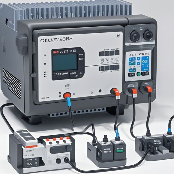
So, let's dive into the world of PLCs and understand their principles. A programmable logic controller is essentially a computer system that interfaces with sensors, actuators, and other control devices to manage complex industrial processes. It consists of several main components:
1、Input/Output Unit (I/O Unit): This is where the user inputs and outputs data from or to the PLC. It includes switches, buttons, and other devices that allow for manual input or output.
2、Central Processing Unit (CPU): The CPU is responsible for processing the data received from the I/O units and making decisions based on this information. It executes algorithms, stores data, and communicates with other components in the PLC.

3、Memory: Storage devices like RAM and Flash memory are used to store instructions and data for the CPU and other components.
4、Power Supply Unit: This is responsible for providing power to all PLC components, including the CPU, memory, and input/output units.
5、Network Interface: Some PLCs may have network connectivity features, allowing them to communicate with other PLCs or external devices through wireless connections like Wi-Fi.
Now, let's talk about the key components of a typical PLC.
1、Programmable Logic Module (PLC Module): This is the physical device that contains the CPU and other circuitry required to implement a specific control algorithm. Each module comes with a unique address code, which allows it to be identified within the PLC network.
2、Input/Output Devices: This section includes various sensors and actuators that detect physical conditions and respond accordingly. For example, pressure sensors measure the pressure in a pipeline, while temperature sensors monitor temperature levels in different areas.
3、Control Systems: PLCs can be connected to various control systems like PID controllers, motion control systems, and communication protocols like Ethernet or Profibus. These connectors enable the PLC to interact with the rest of the industrial automation system.
4、Software Development Kit (SDK): Many PLC manufacturers provide software development kits (SDKs) that allow developers to create custom applications and extend functionality beyond what the hardware itself provides. These kits often come with libraries for common tasks, such as data logging, fault detection, and performance monitoring.
In terms of how PLCs work, they operate based on the principle of state change. When a signal is inputted to the PLC, it triggers a state change, which then affects the output of the system according to the programmed logic. This means that the PLC can take on multiple roles, from a simple relay switch to a complex digital controller.
One of the most significant benefits of using PLCs is their ability to automate complex industrial processes, leading to increased efficiency and productivity. By controlling multiple variables and parameters simultaneously, PLCs can help reduce downtime, minimize maintenance costs, and optimize energy usage.
Another advantage of PLCs is their flexibility. With just a few clicks on the software, you can easily modify the programming code to suit your needs. Whether you need to add new sensors or adjust control parameters, the PLC can accommodate these changes without requiring extensive reprogramming.
Finally, one of the biggest advantages of PLCs is their reliability. Thanks to their built-in redundancy features, they can handle high loads and maintain stability even in challenging environments. This makes them ideal for use in critical applications where downtime could have severe consequences.
In conclusion, Programmable Logic Controllers (PLCs) are incredibly versatile tools for managing industrial processes. Their ability to automate complex systems, improve efficiency, and ensure reliability make them an essential component in any modern production line. So if you're looking for advanced automation solutions, don't miss out on the benefits that PLCs offer!
Content expansion reading:
Content:
Hey there! If you're new to the world of PLCs (Programmable Logic Controllers), or you're looking to brush up on your knowledge, understanding PLC controller wiring diagrams is a crucial step. These diagrams can seem intimidating at first, but once you know what to look for, they're actually pretty straightforward. Let's dive in and break down the basics!

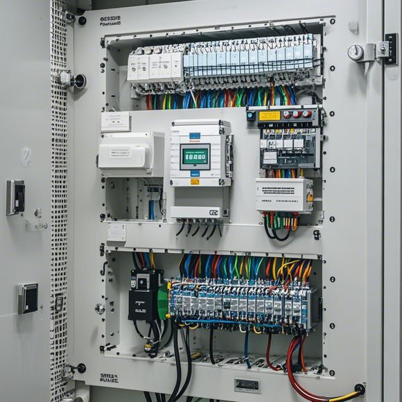
First things first, a PLC controller wiring diagram is a visual representation of the electrical connections and components within a PLC system. It's like a blueprint that shows you how all the parts are connected and what each part does. This includes input and output devices, power supplies, and the PLC itself.
The diagram typically includes:
1、Power Supply: This is where the electrical power comes from to run the PLC. You'll see a symbol for the power source, like a battery or a transformer, and the wires that connect it to the PLC.
2、PLC: The main component! This is where the logic and decision-making happen. The PLC will have various terminals for inputs and outputs.
3、Input Devices: These are the sensors or switches that provide data to the PLC. They could be limit switches, temperature sensors, or any other device that tells the PLC what's happening in the system.
4、Output Devices: These are the devices that the PLC controls. They could be motors, lights, valves, or anything that needs to be turned on or off based on the PLC's instructions.
5、Wiring: The wires that connect everything together are represented by lines in the diagram. They show the path of electrical current from the power supply to the input devices, through the PLC, and out to the output devices.
When you're looking at a PLC controller wiring diagram, here are some tips to help you make sense of it all:
Read the Legend: Every diagram should have a legend that explains what each symbol means. Make sure you understand what each symbol represents before you start trying to interpret the diagram.
Follow the Path: Trace the wires from the power supply to the PLC, then from the PLC to the input devices, and finally from the PLC to the output devices. This will help you understand the flow of information and power.
Identify the Components: Learn to recognize common components like relays, contactors, and transformers. Each has a specific function that's important to understand.
Check for Grounding: Proper grounding is essential for safety and to prevent electrical noise. Look for ground symbols in the diagram to ensure they're connected correctly.
Pay Attention to Ratings: Make sure the devices and wires are rated for the correct voltage and current. Using the wrong size wire or an underrated component can lead to damage or even fire.
Ask Questions: If you're unsure about anything, don't hesitate to ask your supervisor or a more experienced colleague. Safety and proper operation are paramount.
Remember, practice makes perfect. The more wiring diagrams you look at and understand, the more comfortable you'll become with reading and interpreting them. Always refer to the manufacturer's manual or technical documentation for specific information about the PLC and its components.
Articles related to the knowledge points of this article:
Mastering the Art of Plc Controllers: A Comprehensive Guide to Understand and Implement
PLC (Programmable Logic Controller) Control System Basics
Connecting a PLC Controller to Your Computer
PLC Controllers: A Comprehensive Guide to Understanding Their Prices