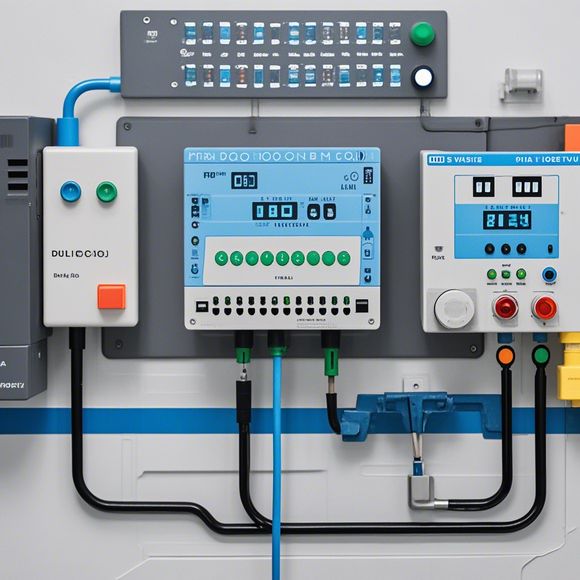
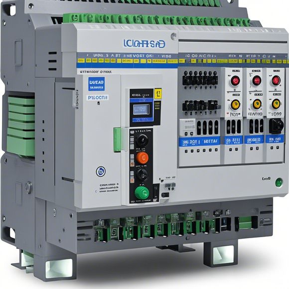
PLC Controller wiring Diagram for Factory Automation
In the field of factory automation, PLC (Programmable Logic Controller) controller wiring diagrams play a crucial role in ensuring smooth operation and efficiency. These diagrams are designed to show the electrical connections between various components such as sensors, actuators, switches, and relays. They provide a clear picture of how these components are interconnected, allowing for easy troubleshooting and modification of the system when necessary.One of the key benefits of using PLC controller wiring diagrams is their ability to simplify complex control systems. By visualizing the connections between various elements of the control system, technicians can quickly identify any potential issues and make appropriate adjustments. This not only reduces downtime but also improves overall system performance.Another advantage of PLC controller wiring diagrams is their flexibility. With the ability to easily add or remove components from the system, they can be adapted to meet the specific needs of different applications. Whether it's adding a new sensor or replacing an old relay, the wiring diagram remains intact, allowing for easy modification without disrupting the overall system.In summary, PLC controller wiring diagrams are critical for ensuring the efficient operation of factory automation systems. With their ability to simplify complex systems and provide flexibility in adaptation, they have become an indispensable tool for modern industrial applications.
Dear all,
I hope this message finds you well. In today's workshop session, I would like to discuss the intricacies of our factory automation system with a focus on its core component: The Programmable Logic Controller (PLC). As we dive into the details of this critical piece in our operations, let us begin by examining the plc controller's wired connections, which play a crucial role in the smooth operation of our industrial machinery and processes.
Firstly, let's start with the basics. A PLC, as the name suggests, is a computerized device that performs logic control functions. Its primary purpose is to automate various industrial systems through precise calculations and decisions made based on input from sensors and actuators. This is where the importance of a well-designed wiring diagram comes into play.
Now, let's delve deeper into the intricacies of the wiring diagram. It forms the backbone of any PLC system, connecting the various components and ensuring seamless communication between them. Here are some key points to consider:

1、Input Devices: These devices capture data from the environment or other machines, such as switches, buttons, or sensors. The wiring diagram should clearly indicate the connection points for these devices and their respective signals.
2、Output Devices: On the other hand, these devices generate signals that are used to control the machinery or processes. Again, the diagram should show where these output signals are connected to ensure they can be properly controlled.
3、Power Connections: Every PLC requires power to operate, and the wiring diagram should clearly indicate the source and distribution of the power. This includes the main power supply and any additional power sources necessary to support the system.
4、Communication Paths: Modern PLC systems often use digital protocols for data exchange, such as PROFIBUS or Ethernet. The wiring diagram should outline the communication paths, including the types of cables used, the network topology, and any security measures required for secure data transmission.
5、Error Handling: In any complex system, there will always be some level of error. The wiring diagram should include provisions for error detection and correction mechanisms, such as redundant connections or fail-safe switches. This ensures that even in the event of a fault, the system remains operational.
6、Maintenance and Testing: Finally, it's essential to have clear guidelines for maintenance and testing procedures. This includes marking the location of spare parts, tools, and testing equipment, as well as indicating how to access and inspect the wiring diagram for signs of wear or damage.
In conclusion, understanding and maintaining a well-crafted wiring diagram is crucial for the success of any PLC-based automation system. By following the tips outlined above, we can ensure that our factories run efficiently and reliably, maximizing productivity and minimizing downtime. So next time you come across an intricate wiring diagram, take a deep breath, relax, and enjoy the journey of understanding it. After all, it's not just about the technical aspects; it's also about fostering a culture of innovation and excellence within our team.
Thank you for your attention to this important topic, and remember, every small step counts towards achieving our shared goals.
Content expansion reading:
Content:

Hey there! If you're new to the world of PLCs (Programmable Logic Controllers), or you're just looking to brush up on your knowledge, understanding PLC controller wiring diagrams is a crucial step. These diagrams can seem intimidating at first, but once you know what to look for, they're actually pretty straightforward.
So, what exactly is a PLC controller wiring diagram? It's a visual representation of the connections between the various components of a PLC system. This includes the power supply, input devices, output devices, and the PLC itself. The diagram shows you how these components are wired together, which is essential for ensuring that your system is functioning correctly.
When you're looking at a PLC controller wiring diagram, the first thing you'll notice is that it's divided into different sections. The power supply section is usually at the top, followed by the input devices, the PLC, and finally, the output devices. Each section is labeled clearly, so you can easily identify what's what.
Input devices are the sensors that provide data to the PLC. They can be switches, buttons, or more complex devices like temperature sensors or proximity switches. Output devices, on the other hand, are the things that the PLC controls, like motors, lights, or solenoids. The PLC itself is the brain of the system, processing the input data and controlling the output devices accordingly.
The wiring diagram will show you the specific terminals on the PLC that are connected to each input and output device. For example, it might show that input device 1 is connected to PLC input terminal 12, and output device 3 is connected to PLC output terminal 24. This is where the detail of the diagram comes in handy, as it ensures that you connect everything correctly during installation.
It's important to note that PLC controller wiring diagrams can vary widely depending on the manufacturer and the specific model of the PLC. However, the basic principles remain the same across all diagrams. Always refer to the manufacturer's manual for the specific wiring instructions for your PLC model.
When working with PLC controller wiring diagrams, it's also a good idea to have a multimeter handy. This tool can help you troubleshoot any issues that might arise during installation or maintenance. For instance, if a particular output device isn't working, you can use the multimeter to check the continuity of the wiring and ensure that there are no loose connections or shorts.
Remember, safety is paramount when working with PLCs and their wiring. Always ensure that the power is off before you start making any connections, and use the appropriate tools and safety gear.
In conclusion, PLC controller wiring diagrams are a vital part of any industrial control system. They provide a clear and concise guide to the connections between devices, ensuring that your system runs smoothly and efficiently. Whether you're a seasoned pro or just starting out, taking the time to understand these diagrams will serve you well in your career in automation.
Articles related to the knowledge points of this article:
Mastering the Art of Plc Controllers: A Comprehensive Guide to Understand and Implement
PLC Controller Wiring Guideline
Connecting a PLC Controller to Your Computer
PLC Controllers: A Comprehensive Guide to Understanding Their Prices