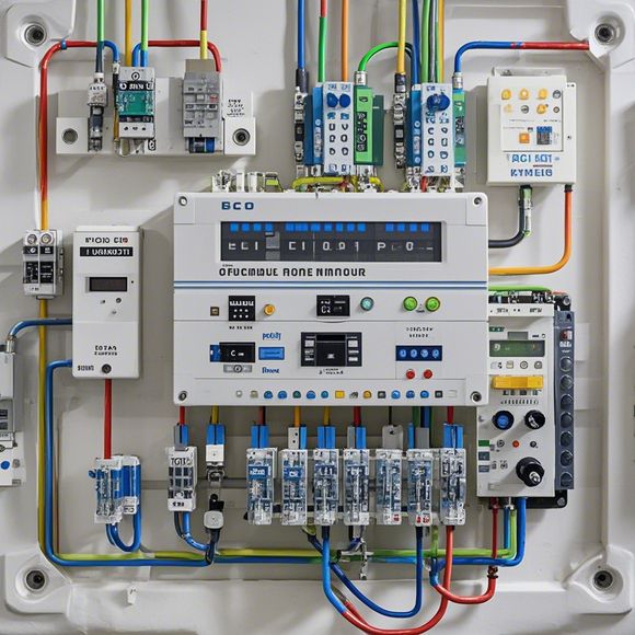
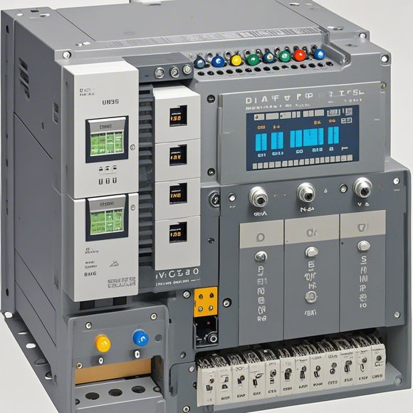
PLC Controller Wiring Diagram
Sure, here's an example of a PLC Controller Wiring Diagram in English:---**Wiring Diagram for PLC Controller**The wiring diagram for our PLC controller is quite straightforward. The main components are the Input/Output (I/O) modules, which connect to various sensors and actuators in the system. There are also several relays and switches that control the flow of power and signal. The connections between these components are carefully designed to ensure reliable operation and minimize potential issues.The first step is to identify all the I/O modules on the controller. Each module has specific pins that need to be connected to the appropriate sensors and actuators. Once this is done, we can begin connecting wires from each sensor or actuator to the corresponding module on the controller. We also need to connect power lines from external sources to the controller.Finally, we test the wiring by running tests to verify that the system is operating correctly. If any issues arise during the testing process, we will need to make adjustments to the wiring diagram and retest until the system is fully functional.---Note: This is just a general outline for a PLC Controller Wiring Diagram. The actual layout may vary depending on the specific requirements and design of the system being built.
As a forward-thinking exporter, it's essential that you not only understand the intricacies of your products but also have a thorough knowledge of their international markets. One crucial aspect of this is having accurate and clear documentation about how to wire the various components of your product. This includes knowing how to connect the PLC controller to its various inputs and outputs, as well as the connections between different parts of the system. In this guide, we will walk you through the process step by step, ensuring that you can confidently handle any wiring challenges that come your way. Whether you're dealing with a small-scale DIY project or need expert help for a larger scale manufacturing facility, our comprehensive guide will help you achieve seamless connectivity and reliable performance. So, without further ado, let's get started!
Content expansion reading:

Content:
Hey there! If you're new to the world of PLCs (Programmable Logic Controllers), or you're just looking to brush up on your knowledge, understanding PLC controller wiring diagrams is a crucial step. These diagrams can seem intimidating at first, but once you know what to look for, they're actually pretty straightforward.
So, what exactly is a PLC controller wiring diagram? It's a visual representation of the electrical connections between the various components of a PLC system. This includes the power supply, input devices, output devices, and the PLC itself. The diagram shows you how these components are connected and how they interact with each other.
When you're looking at a PLC controller wiring diagram, the first thing you'll notice is that it's divided into different sections. The power supply section is usually at the top, followed by the input devices, the PLC, and finally, the output devices. Each section is labeled clearly, so you can easily identify what's what.

Input devices are the sensors that provide data to the PLC. They can be switches, buttons, or more complex devices like temperature sensors or proximity switches. Output devices, on the other hand, are the actuators that the PLC controls. This could be anything from a motor to an indicator light.
The PLC itself is the brain of the system. It's where the programming logic lives, and it's responsible for interpreting the input data and controlling the output devices accordingly. The wiring diagram will show you the connections between these inputs and outputs and the specific PLC modules they're connected to.
One important thing to remember is that PLC controller wiring diagrams can vary widely depending on the manufacturer and the specific application. However, the basic principles remain the same. Always refer to the manufacturer's manual or documentation for the specific wiring instructions for your PLC model.
When working with PLC controller wiring diagrams, it's also important to understand the symbols used. Different symbols represent different types of devices and connections. For example, a circle with a line through it represents a normally open switch, while a circle with a line across it represents a normally closed switch.

In summary, PLC controller wiring diagrams are a vital tool for anyone working with PLC systems. They provide a clear and concise way to understand how all the components fit together and how they interact. By familiarizing yourself with these diagrams, you'll be better equipped to troubleshoot issues, make repairs, and even expand or modify your PLC system as needed. So, take some time to study them, and you'll be on your way to becoming a PLC pro!
Articles related to the knowledge points of this article:
How to Use a PLC Controller for Your Business
Plumbers Rule! The Role of PLC Controllers in the World of Waterworks
The Role of Programmable Logic Controllers (PLCs) in Foreign Trade Operations
Connecting a PLC Controller to Your Computer
PLC Controllers: A Comprehensive Guide to Understanding Their Prices