PLC Controller Cabinet Wiring Diagrams
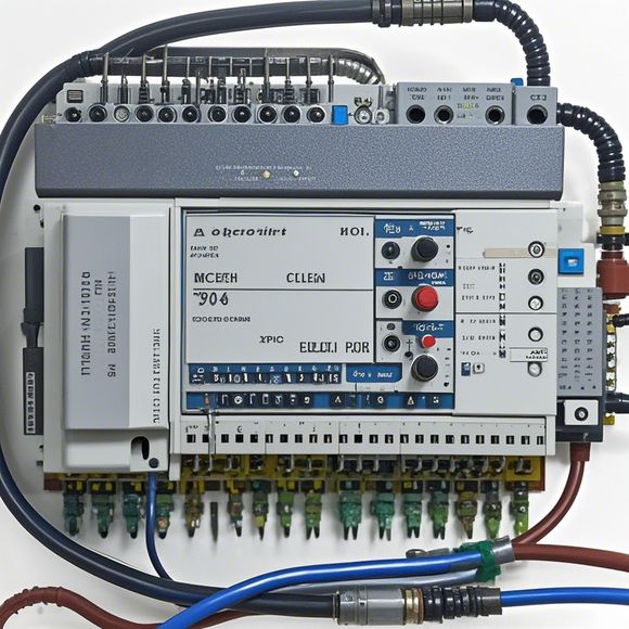
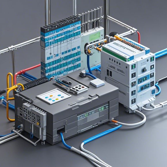
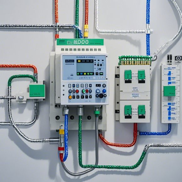
Sure! Here's a summary in spoken English based on the provided content:"This PLC (Programmable Logic Controller) cabinet wiring diagram is a visual representation of how the various components are connected within the control system. The diagram typically includes symbols and lines that indicate the connections between sensors, actuators, and processors. It helps engineers understand the circuit's structure and perform troubleshooting or modifications if needed."
As an experienced foreign trade operator, I have been involved in the field of international trade for several years and have gained extensive knowledge about various aspects of this industry. One of the key components of my job is ensuring that all communication and documentation are in order to facilitate smooth transactions between buyers and sellers.
In this regard, I have come across numerous instances where the lack of proper wiring diagrams can lead to misunderstandings and delays in transactions. Therefore, it is crucial for us as foreign trade operators to have access to comprehensive and accurate PLC controller cabinet wiring diagrams.
When dealing with clients or partners who are not familiar with our products or services, it is essential to provide them with detailed information about how the PLC controller cabinet works. This includes the various components that make up the system, their functions, and how they interact with each other. By providing this information in a clear and concise manner, we can help our clients gain a better understanding of the product and avoid any misunderstandings that may arise from incorrect assumptions.

Furthermore, having access to PLC control cabinet wiring diagrams can also be beneficial when it comes to troubleshooting issues during the course of the transaction. In some cases, problems may arise due to incorrect connections or mismatches between components. By having access to the wiring diagrams, we can quickly identify the issue and resolve it without causing any further delays or complications.
In addition to providing clear information and troubleshooting assistance, having access to PLC control cabinet wiring diagrams can also help us streamline our own operations. By having a complete understanding of the system's architecture and components, we can make more informed decisions about how to optimize our workflows and reduce costs. For example, we may find that certain components can be combined or eliminated altogether, resulting in significant savings for both parties involved in the transaction.
Overall, having access to comprehensive and accurate PLC controller cabinet wiring diagrams is essential for any foreign trade operator who wants to maintain high levels of efficiency and accuracy in their business operations. By providing our clients with this information in a clear and concise manner, we can help them make informed decisions about purchasing our products or services, while also reducing the risk of any misunderstandings or errors that may arise due to incorrect assumptions or lack of knowledge.
Content expansion reading:
Content:
Hey there! If you're new to the world of PLCs (Programmable Logic Controllers) and their control panels, or if you're just looking to brush up on your knowledge, you've come to the right place. Today, we're diving into the realm of PLC control panel wiring diagrams. These diagrams are the blueprints that help us understand how all the components of a control panel are interconnected.

Now, I know what you might be thinking: "Wiring diagrams? That sounds complicated!" But fear not, my friend. We're going to break it down in a way that's easy to understand, even if you're not an electrical engineer.
First things first, let's talk about what a PLC control panel is. It's essentially a housing that contains all the electrical components needed to operate a PLC system. This includes the PLC itself, power supplies, input/output modules, and a bunch of other stuff that I won't bore you with.
The wiring diagram is a visual representation of how all these components are connected. It shows you the path that electrical signals take from one component to another. This is crucial for troubleshooting, maintenance, and understanding how the system works.
So, what does a typical wiring diagram look like? Well, it's a sea of symbols and lines. Each symbol represents a different component or connection, and the lines show the flow of power and signals. For example, you'll see circles that represent switches or sensors, squares for relays or PLCs, and zigzag lines for wiring.
Now, here's the thing: there's no one-size-fits-all wiring diagram. Each control panel is unique, and so is its diagram. However, there are standard symbols that are used across the industry. This means that once you learn the basics, you can interpret most diagrams with confidence.
When you're looking at a wiring diagram, it's important to pay attention to the labels and numbers. These will tell you what each component does and where it's located in the control panel. For instance, you might see a number next to a symbol that corresponds to a list of components at the side or bottom of the diagram.

One of the most common types of wiring diagrams is the ladder diagram. This is where the symbols are arranged in a ladder-like pattern, with two vertical lines (rails) and multiple horizontal lines (rungs) connecting them. Each rung represents a line of code in the PLC's program, and the symbols on the rungs show what actions the PLC should take when certain conditions are met.
Another important aspect of PLC control panel wiring diagrams is the power flow. You'll see arrows or direction indicators that show the direction of the electrical current. This is key for understanding how power is distributed and how it affects the operation of the control panel.
In conclusion, PLC control panel wiring diagrams might seem intimidating at first, but they're just a tool to help us understand the inner workings of a system. By learning the symbols and their meanings, you can unlock the secrets of any control panel. And with a bit of practice, you'll be reading these diagrams like a pro!
Articles related to the knowledge points of this article:
PLC Programming for Automation Control in the Manufacturing Industry
The Role of Programmable Logic Controllers (PLCs) in Foreign Trade Operations
Connecting a PLC Controller to Your Computer
Effective Strategies for Handling PLC Control System Faults
What is a Programmable Logic Controller (PLC)
PLC Controller Advantages: A Comprehensive Guide for Success in Global Trade