Understanding the PLC Circuit Diagram: A Guide to Mastering the Technical Terminology
Understanding PLC (Programmable Logic Controller) circuit diagrams is a fundamental skill for any engineer. Here's a simple guide to mastering this technical jargon:1. **Read the Circuit Diagram**: Begin by studying the circuit diagram carefully. This will help you understand what components are connected and in what order.2. **Identify the Signals**: Pay attention to the signals that flow through each component. These include input signals (indicating what needs to happen) and output signals (indicating what happens as a result of these inputs).3. **Understand the Components**: Learn the names and functions of the various components in the circuit diagram. This includes sensors, actuators, switches, and so on.4. **Follow the Control Flow**: Trace the path that control signals take from the input devices to the output devices. This will help you understand how the system operates.5. **Master the Terminology**: Finally, practice using the terminology used in the diagram. This includes acronyms (like PID for Proportional-Integral-Derivative), symbols, and specific terms like "ON" (on), "OFF" (off), and "HIGH" (high).By following these steps, you'll be able to read and interpret PLC circuit diagrams with ease. Remember, it takes time to become proficient at something, so keep practicing!
Dear colleagues,
As a seasoned professional in the field of foreign trade operations, it is essential for us to have a deep understanding of the plc circuit diagram. This knowledge will undoubtedly enhance our ability to navigate complex machinery and systems, ensuring efficient operation and reduced downtime. In this article, I aim to guide you through the key terms and concepts that make up the PLC circuit diagram, providing insights into how we can effectively read and interpret such diagrams.

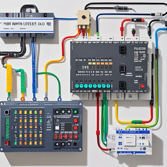
At its core, the plc (programmable logic controller) circuit diagram is a visual representation of the electrical connections within a machine or system. It serves as a blueprint for the flow of power and data, enabling us to understand the workings of various components. By mastering these terminologies, we can identify issues before they escalate, leading to potential breakdowns or operational inefficiencies.
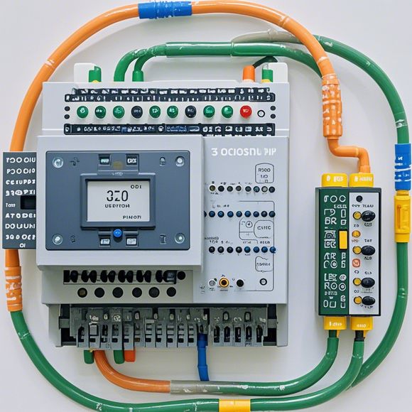
Firstly, let's delve into the basic elements of a PLC circuit diagram. These include the main components such as the CPU (central processing unit), input/output modules, and communication modules. Each component plays a distinct role in the overall functioning of the device. For example, the CPU handles the processing of instructions and data, while the input/output modules manage the connection between the system and external devices. The communication modules facilitate the exchange of information between different parts of the system.
Now, let's delve deeper into some of the most commonly used terminologies found in PLC circuit diagrams. One such term is "I/O," which stands for "input/output." This refers to the physical connections that enable the transfer of signals from sensors or actuators to the CPU. Another important term is "PLC," which stands for "programmable logic controller." This refers to the hardware and software components that allow us to create custom programs for controlling various functions within our machines.
In addition to these technical terms, there are also several other crucial ones that we should familiarize ourselves with. For instance, "A/D" stands for "analog-to-digital conversion," which refers to the process of converting analog signals into digital format for easier processing by the CPU. Similarly, "D/A" stands for "digital-to-analog conversion," which refers to the reverse process of converting digital signals back into analog form for output purposes.
Another term that is often encountered in PLC circuit diagrams is "PID," which stands for "proportional-integral-derivative." This is an algorithm used in industrial control applications to regulate variables based on their past values. PID controllers are particularly useful in situations where we need to achieve precise control over temperature, pressure, or other continuous variables.
Finally, let's take a look at some of the more advanced terminologies that may be found within PLC circuit diagrams. For example, "PLCS" stands for "programmable logic switches," which refer to specialized hardware components designed to perform specific functions within a PLC system. Similarly, "IEC" stands for "international electrotechnical commission," which is a body that sets standards for electrical and electronic products worldwide.
Now, let's consider some practical examples to illustrate the application of these terminologies within a real-world scenario. Imagine you are tasked with maintaining a manufacturing line that requires precise control over multiple variables such as temperature, pressure, and speed. To achieve this goal, you would need to use a PLC system that incorporates advanced control algorithms such as PID. Additionally, you would need to ensure that all inputs and outputs are properly connected and configured to meet the requirements of your specific application.
In conclusion, understanding the PLC circuit diagram is crucial for anyone working in the field of foreign trade operations. By mastering the key terms and concepts that underpin such diagrams, we can gain a competitive edge when dealing with complex machinery and systems. Remember, investing time in learning about these topics will ultimately pay off in terms of efficiency, productivity, and reduced downtime. So, grab a pen and notebook, and let's get started on unraveling the mysteries of PLC circuit diagrams together!
Content expansion reading:
Content:
Hey there, fellow tech enthusiasts! Today, we're diving into the world of Programmable Logic Controllers (PLCs) and how to make sense of those complex circuit diagrams that often leave us scratching our heads. Don't worry, with a little guidance, you'll be decoding PLC diagrams like a pro in no time. So, let's get started!
First things first, what is a PLC? In simple terms, it's a type of industrial computer designed to control and automate various electromechanical processes. PLCs are tough, they can handle harsh environments, and they're super flexible when it comes to programming.
Now, let's talk about those circuit diagrams. A PLC circuit diagram is a blueprint that shows the electrical connections between different components of the PLC system. It's like a map that tells you where everything is and how it all fits together.
Here's a step-by-step guide to help you unravel the mysteries of a PLC circuit diagram:

1、Start with the Power Supply:
- Look for the power supply section. This is where the incoming AC or DC power is converted into the appropriate voltage for the PLC.
- You'll see symbols for the power input, transformers, and any rectifiers or converters.
2、Find the PLC Chassis:
- The PLC chassis is the heart of the system. It houses the processor, memory, and I/O modules.
- Look for a rectangular box with inputs and outputs labeled on the sides.
3、Identify the Inputs and Outputs:
- Inputs are how the PLC "sees" what's happening in the real world. They can be switches, sensors, or any other device that provides data to the PLC.
- Outputs are how the PLC "acts" on the world. They can be relays, motors, lights, or anything that needs to be controlled.
4、Understand the I/O Modules:
- I/O modules are the connectors between the PLC and the physical world.
- They're usually labeled as "input" or "output" modules and are plugged into the PLC chassis.
5、Check for Specialty Modules:
- Some PLCs have specialty modules for specific tasks like communication, timing, counting, or analog processing.

- These modules will have their own unique symbols and functions.
6、Look for Wiring and Connections:
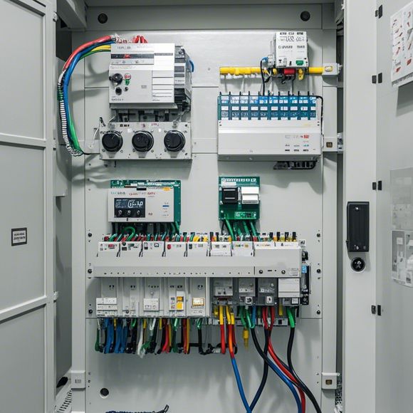
- The wiring between components is crucial. It shows how the power and signals flow through the system.
- Pay attention to the wire colors and the symbols for connectors and terminals.
7、Read the Legend:
- Every PLC circuit diagram comes with a legend that explains what the symbols mean.
- Make sure you understand what each symbol represents before you start interpreting the diagram.
8、Follow the Flow:
- Once you've identified the components, follow the flow of the diagram from power input to outputs.
- This will help you understand how the PLC processes information and controls the system.
Remember, practice makes perfect. The more PLC circuit diagrams you study, the better you'll become at interpreting them. And don't be afraid to ask questions or seek help from more experienced colleagues.
So, there you have it—a quick guide to understanding PLC circuit diagrams. With a bit of knowledge and a lot of curiosity, you'll be able to tackle even the most complex diagrams with confidence. Happy troubleshooting!
Articles related to the knowledge points of this article:
PLC Controller for Manufacturing Automation
The cost of a PLC Controller: A Comprehensive Analysis
How to Use a PLC Controller for Your Business
PLC (Programmable Logic Controller) Control System Basics