PLC Module Wiring Diagram Guide
Sure, here's a brief summary in English based on your provided content:"This guide provides step-by-step instructions on how to assemble and wire the PLC (Programmable Logic Controller) module. The guide is designed to help you understand each component of the system, including the power supply, sensors, actuators, and control algorithms. It includes diagrams and schematics to assist with the wiring and installation process."
Dear all,
As we embark on our journey as an experienced and knowledgeable trader in the global marketplace, it is crucial to understand the intricate details that underlie the operation of PLC (Programmable Logic Controller) modules. A thorough knowledge of their wiring diagrams is paramount for effective implementation and maintenance, ensuring optimal performance and minimizing downtime.

The PLC module wiring diagram serves as a roadmap that guides us through the installation process, detailing each component's precise connection points and their interrelationships. It is akin to a blueprint, outlining the physical layout of the PLC system, enabling us to visualize how components are arranged and connected within the system. This understanding enables a seamless integration of different systems and facilitates troubleshooting when issues arise.
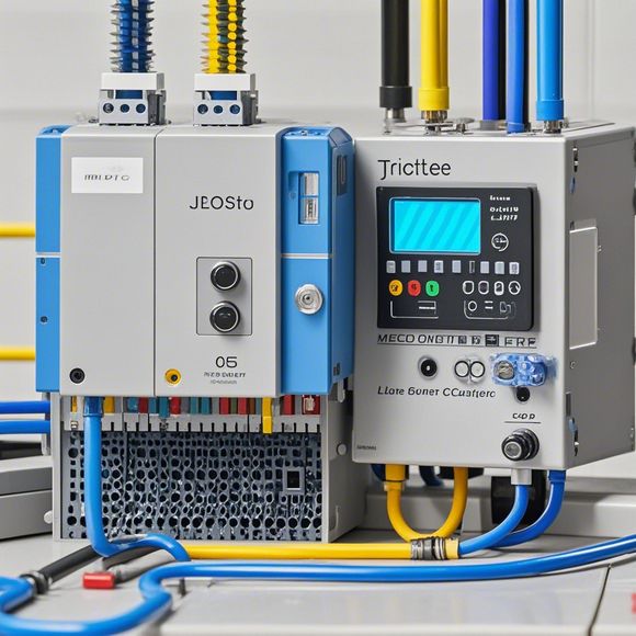
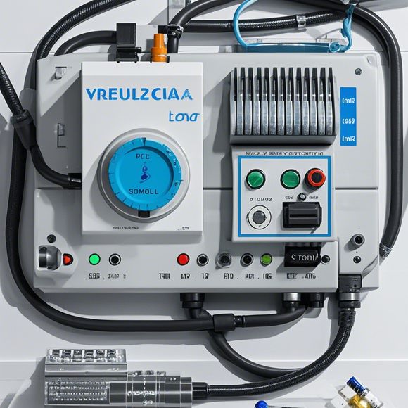
Let us dive into the intricacies of this essential documentation. The first step is to comprehend the basic structure of the PLC module wiring diagram. It typically consists of several sections, including the main control panel, input/output modules, sensors, and actuators. Each section is labeled with its corresponding function, making it easy to identify the components involved.
One critical aspect to note is the placement of the PLC unit within the system. It should be strategically positioned to optimize the signal flow and minimize interference. This involves carefully selecting the appropriate location based on factors such as power supply availability, noise levels, and proximity to other devices. Proper placement ensures a smooth and reliable workflow.
Now, let us delve into the connections between various components. Each module has specific connections required for communication and data exchange. For example, a sensor may have inputs for temperature, pressure, or flow rate, while an output may involve controlling actuators or displaying data on a monitor. These connections must be accurately mapped to ensure seamless integration.
Moreover, the PLC module wiring diagram often includes additional features such as alarms, safety switches, and protective circuits. These components are crucial for alerting operators to potential hazards or malfunctions, providing an early warning to minimize downtime.

In conclusion, the PLC module wiring diagram is a vital tool for anyone working with PLC systems. By understanding its basic structure and connections, we can confidently install and maintain our systems, ensuring optimal performance and reliability. Let us embrace this knowledge as we continue to navigate the ever-changing landscape of the global market, confident in our ability to adapt and succeed in every challenge that comes our way.
Thank you for your time and attention. I hope this guide has been helpful in enhancing your understanding of the complexities involved in PLC module wiring. If you have any further questions or need assistance with any aspect of this project, do not hesitate to reach out. Together, we can overcome any obstacle and achieve great success.
Content expansion reading:
Articles related to the knowledge points of this article:
PLC Controller for Manufacturing Automation
The cost of a PLC Controller: A Comprehensive Analysis
PLC Programming for Automation Control in the Manufacturing Industry
How to Use a PLC Controller for Your Business
The Role of Programmable Logic Controllers (PLCs) in Foreign Trade Operations