PLC Input Output (I/O) Wiring Diagram Guide
Sure, I can help with that. Can you provide me with the content you want to be summarized?
Hello, everyone! Today, I'm excited to talk about a crucial topic for our business – the PLC Input Output (I/O) wiring diagram. It's an essential tool that helps us connect our devices and systems together in a seamless manner. So let's dive right into it!
When we start building something, especially with PLCs, we need to know where everything goes. This includes knowing how to connect wires to each other and where they should be placed. That's where the wiring diagram comes in. It's like a blueprint of how everything should be connected, so we can make sure everything works properly.
So, what exactly is a PLC I/O wiring diagram? Well, it's simply a visual representation of the connections between the various components in a PLC system. It tells you where each wire should come from, go to, and where it should be connected to. And this is all done using simple symbols and lines.

Now, imagine having to figure out how to connect all those wires manually. You might end up getting frustrated or even damaging your equipment in the process. But with a good wiring diagram, all that hassle is taken care of. We can easily follow the diagram, making sure that everything is wired correctly and safely.
But that's not all. A good wiring diagram also helps us troubleshoot any issues that may arise during the installation process. If there's something wrong, we can quickly identify the problem and fix it without wasting time on unnecessary steps.
So, if you're new to this whole PLC thing, don't worry. With a few basic tools and some patience, you can get started with your own wiring diagrams. And once you've mastered them, you'll be able to build anything from a simple circuit to a complex system with ease.
So let's get back to the main topic – the PLC I/O wiring diagram. It's a powerful tool that can take your engineering skills to the next level. So why wait? Get started today and see how easy it is to create your own wiring diagrams!
Content expansion reading:
Content:
Hey there! If you're new to the world of PLCs (Programmable Logic Controllers), one of the first things you'll need to wrap your head around is the input/output wiring diagrams. These diagrams are like the blueprint that tells you how to connect all the different parts of a PLC system to the outside world. It's like a language, and once you learn it, you can talk to machines!
So, what exactly is an input/output wiring diagram? Well, it's a visual representation of how the PLC communicates with the devices it controls or the sensors that feed it data. Inputs are like the eyes and ears of the PLC, while outputs are like its hands, controlling the machinery.

Let's break it down:
Inputs: These are the points where the PLC receives information from sensors, switches, or other devices. They can be digital (like a simple on/off switch) or analog (like a temperature sensor that provides a continuous value).
Outputs: These are the points where the PLC sends signals to actuators, motors, or lights. Again, they can be digital (like a relay that turns something on or off) or analog (like a valve that needs to be opened or closed to a specific position).
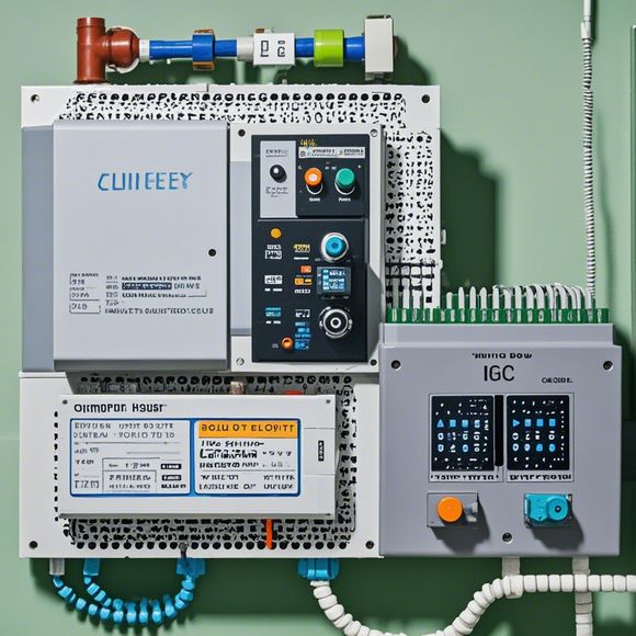
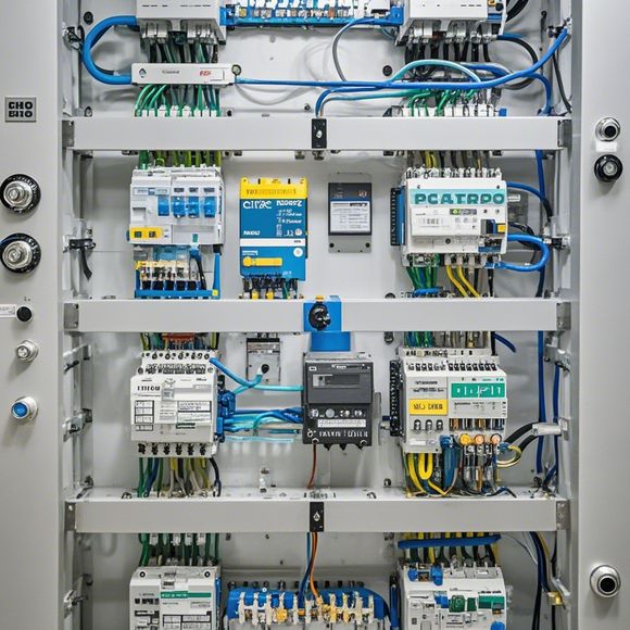
The wiring diagram will show you the specific pins on the PLC that correspond to these inputs and outputs, as well as the wiring that connects them to the external devices. It's crucial to follow these diagrams carefully to ensure that the PLC is communicating correctly with everything else.
Here's a quick rundown of what you might see on a typical PLC input/output wiring diagram:
- Terminal Numbers: These are the specific locations on the PLC where wires are connected.
- Device Type: This tells you what kind of device is connected to each terminal (e.g., sensor, motor, etc.).
- Wiring Instructions: This includes the wire size, color coding, and any special instructions for wiring.

- Power Supplies: The diagram will show where the power is coming from and how it's distributed.
- Grounding: Proper grounding is essential for safety and to prevent electrical noise.
When you're looking at a wiring diagram, it's important to pay attention to the symbols used. Different symbols represent different types of devices and connections. For example, a circle with a line through it might represent a normally open switch, while a circle with a line with a plus inside might represent a normally closed switch.
It's also worth noting that PLCs can have different types of inputs and outputs. You might have direct-wired, isolated, or even smart I/O modules that can do more complex processing.
Remember, safety is paramount when working with PLCs and electrical systems. Always follow the manufacturer's guidelines, use the correct tools and wear appropriate personal protective equipment. If you're unsure about anything, it's better to ask for help from a more experienced colleague or consult the manufacturer's manual.
In conclusion, understanding PLC input/output wiring diagrams is essential for anyone working with PLCs. It's a skill that takes time to master, but with practice, you'll be able to read and interpret these diagrams like a pro. So, grab a diagram, a multimeter, and let's start talking to some machines!
Articles related to the knowledge points of this article:
PLC Controller Selection Guide for Foreign Trade Operations
The cost of a PLC Controller: A Comprehensive Analysis
Plumbers Rule! The Role of PLC Controllers in the World of Waterworks
Connecting a PLC Controller to Your Computer
PLC Controllers: A Comprehensive Guide to Understanding Their Prices