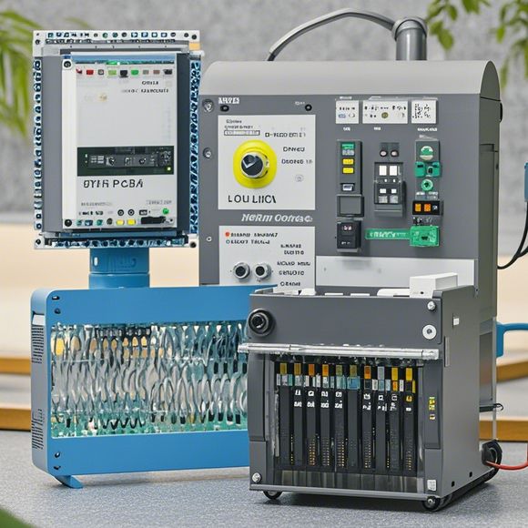
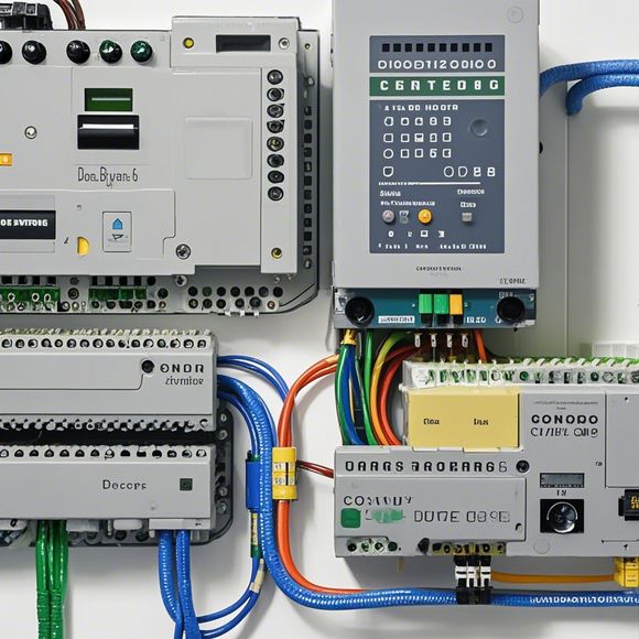
PLC Controller Wiring Diagram: An Insight into the Art of Control
Sure, here's an overview of a PLC controller wiring diagram and how it contributes to the art of control:A PLC (Programmable Logic Controller) is a powerful tool for managing industrial processes. A wiring diagram is a visual representation of how different components are interconnected in the system. In this case, we're looking at a simple PLC controller wiring diagram that shows how the various components are wired together to form a functional system.The diagram includes labels and arrows to indicate the direction of power flow and communication between components. For example, one end of a power cable is connected to a power supply, and the other end connects to a component that uses the power. Similarly, there may be lines labeled "input" or "output," indicating where sensors or actuators are connected.The purpose of the diagram is to help engineers understand how the system functions and troubleshoot any issues if needed. By examining the diagram, they can identify potential problems and make adjustments accordingly. Overall, a well-designed wiring diagram is essential for ensuring the reliability and efficiency of PLC systems.
As an experienced trader in the global marketplace, understanding the intricate world of industrial automation is crucial. One aspect that cannot be overlooked is the role of programmable logic controllers (PLCs) in managing complex processes and ensuring efficiency across a range of industries. In this conversation, we dive deep into the intricacies of PLC controller wiring diagrams, exploring their significance in the operation of modern manufacturing systems.
The first step towards understanding how PLCs function is to understand what these devices are and how they integrate with the rest of the industrial infrastructure. PLCs are digital control units designed to manage various tasks, from simple switches and relays to complex algorithms. They are highly adaptive and can handle a wide range of inputs and outputs, making them ideal for automating industrial processes.
When it comes to wiring, the PLC controller's design involves careful consideration of electrical connections. The diagram provided will show you how each component fits into the overall system, from the input sensors to the output actuators, all working in harmony to produce the desired results.
One important aspect of the wiring diagram is the identification of the power sources and their distribution within the system. It is vital that the correct voltage levels are maintained throughout the system, as any fluctuation can lead to undesired outcomes. Additionally, proper grounding practices must be followed to ensure safety and minimize the risk of electrocution.

The next step is to understand the various types of wiring used within the system. There are different categories of wiring such as AC, DC, and mixed, each with its own set of benefits and drawbacks. For example, AC wiring allows for greater flexibility in terms of location and placement, while DC wiring offers faster response times due to its lower power consumption.
In terms of connecting components, there are specific pins and connectors that must be matched properly. This requires a thorough understanding of the manufacturer's specifications and ensuring that the correct type and quantity of wires are used. Mismatches can lead to circuit failures or other operational issues.
Once the wiring diagram is complete, testing becomes an essential part of the process. It involves verifying that the system is working as intended by monitoring outputs, checking for errors, and adjusting settings as necessary. This testing should be done under controlled conditions to ensure reliability and minimize risks associated with field deployment.
Another critical aspect of PLC controller wiring diagrams is the need for maintenance and repair. With the increasing complexity of modern industrial systems, regular inspections and updates are essential to ensure continued operation at optimal levels. Maintenance activities may include replacing worn-out components, updating programming, or reconfiguring the system to address changing requirements or technological advancements.
Finally, one key point to remember is the importance of communication between PLC systems and other industrial components. As automation systems become more integrated, ensuring seamless data exchange and synchronization becomes crucial for maintaining high-quality production outcomes.
In summary, the PLC controller wiring diagram serves as a vital tool for understanding and maintaining the functionality of modern industrial automation systems. By carefully studying this diagram, one can gain valuable insights into the workings of the system and identify potential areas for improvement or optimization. Whether you are a seasoned professional or just starting out, understanding the intricacies of PLC controller wiring diagrams can help you navigate the complexities of industrial automation with confidence and expertise.
Content expansion reading:

Content:
Hey there! If you're new to the world of PLCs (Programmable Logic Controllers), or you're just looking to brush up on your knowledge, understanding PLC controller wiring diagrams is a crucial step. These diagrams can seem intimidating at first, but once you know what to look for, they're actually pretty straightforward.
So, what exactly is a PLC controller wiring diagram? It's a visual representation of the connections between the various components of a PLC system. This includes the power supply, input devices, output devices, and the PLC itself. The diagram shows you how these components are wired together, which is essential for ensuring that your system is functioning correctly.
When you're looking at a PLC controller wiring diagram, the first thing you'll notice is that it's divided into different sections. The power supply section is usually at the top, followed by the input devices, the PLC, and finally, the output devices. Each section is labeled clearly, so you can easily identify what's what.
Input devices are the sensors that provide data to the PLC. They can be switches, buttons, or more complex devices like temperature sensors or proximity switches. Output devices, on the other hand, are the things that the PLC controls, like motors, lights, or solenoids. The PLC itself is the brain of the operation, processing the input data and controlling the output devices accordingly.
The wiring diagram will show you the specific connections between these components. For example, it will show you which input channels are connected to which input devices, and which output channels are connected to which output devices. It will also show you the power connections, both the incoming power and the distribution within the PLC.
One important thing to look for in a PLC controller wiring diagram is the function blocks. These are symbols that represent the different components and their functions. For instance, a switch might be represented by a simple on/off symbol, while a temperature sensor might have a more complex symbol that includes a thermometer. Understanding these symbols is key to interpreting the diagram.

Another thing to keep in mind is that PLC controller wiring diagrams can vary widely depending on the manufacturer and the specific application. However, the basic principles remain the same. Power in, input devices, PLC, and output devices.
If you're ever unsure about a particular wiring diagram, don't hesitate to reach out to the manufacturer or consult with a professional. They can provide you with additional guidance and help you understand any specific notations or symbols used in their diagrams.
Remember, safety is paramount when working with PLC systems. Always ensure that the power is off before making any connections, and never attempt to modify a wiring diagram without proper training and authorization.
So there you have it! PLC controller wiring diagrams are a vital tool for ensuring that your industrial control system is running smoothly. By understanding the basics of these diagrams, you'll be better equipped to troubleshoot issues, make repairs, and keep your system running at peak performance.
Articles related to the knowledge points of this article:
PLC Programming for Automation Control in the Manufacturing Industry
How to Use a PLC Controller for Your Business
PLC (Programmable Logic Controller) Control System Basics
The Role of Programmable Logic Controllers (PLCs) in Foreign Trade Operations
PLC Controllers: A Comprehensive Guide to Understanding Their Prices