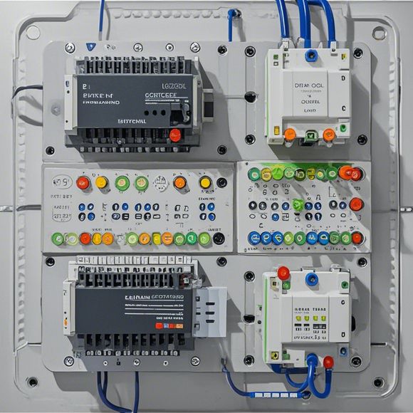
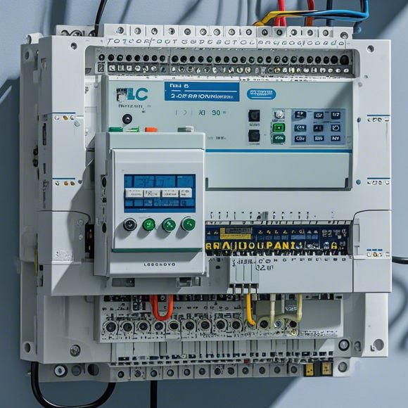
Introduction to PLC Input/Output Wiring Diagrams
In this brief overview, we'll explore the basics of Programmable Logic Controller (PLC) input/output wiring diagrams, a crucial component in the control systems used in industrial environments.PLCs are digital controllers that can be programmed to perform complex tasks. They are often used in manufacturing processes, where they manage the flow of materials and equipment. The wiring diagrams for PLCs contain all the information needed to understand how the various inputs and outputs of the PLC are connected to each other and to the physical devices they control.These diagrams are typically drawn using standardized symbols and labels. For example, a "+" symbol might represent an input signal, while a "-" might indicate an output signal. The connections between different components are also depicted, such as the connection between a sensor and a control element or between two actuators.Understanding these diagrams is important because it helps in troubleshooting problems and ensuring that the PLC is functioning correctly. It also allows engineers to quickly make changes to the system if necessary, without having to physically modify the wiring.Overall, the input/output wiring diagrams for a PLC are a vital tool for any industrial technician or engineer. By understanding how these diagrams work, you can effectively manage and maintain your control systems, ensuring that they operate at optimal performance levels.
Hello, everyone! Today, I'm going to talk about a critical aspect of our business - the PLC input/output wiring diagrams. These diagrams are essential for understanding how data moves between different components within a process control system. Without them, it would be like trying to drive a car without a map – you might get there, but you wouldn’t know exactly where you were headed. So let's dive right in and see how we can navigate these complex networks with ease.
First off, let's start by breaking down what we mean when we say “plc” (programmable logic controller). It's a device that sits at the heart of your industrial automation system. Think of it as the brain that controls everything from heating up a pot of water to turning off a machine when it's done its job. The PLC takes in information from sensors, analyzes it, and then sends out commands to actuators – motors, valves, pumps, etc. – based on those inputs. And all this happens through a series of wires, which we call the input/output (I/O) connections.
Now, let's talk about the input/output wiring diagram. Picture it as a roadmap that shows you exactly where each piece of information is coming from and going to. For example, if you have an oven that needs to heat up to a certain temperature, you'd have a sensor connected to the PLC that reads that temperature and sends it over the wires. Then, the PLC interprets this reading and decides what action to take. If the oven isn't hot enough, the PLC could turn on the fan, or if too hot, turn it off. This is where the I/O wiring plays such a crucial role.
So let's talk about what we need to pay attention to when creating these diagrams. Firstly, we have to ensure that every piece of information flows correctly. This means making sure that the sensors read the correct values, the PLC processes them correctly, and the actuators respond accordingly. Secondly, we need to consider safety measures. For instance, we should never connect a power line to a non-insulated wire, as this could lead to a short circuit and possible explosions. Thirdly, we must ensure that our diagrams are accurate. We don’t want any errors to cause problems in the production line. Fourthly, we need to keep track of the wiring so that we can easily identify and fix any issues. Fifthly, we should always follow the latest standards and regulations for electrical installations. Sixthly, we should make sure that the diagrams are easy to understand for anyone who might need to work on them later. Seventhly, we should consider the future and make sure that our wiring is flexible enough to accommodate changes in technology and equipment. Finally, we should also take into account aesthetics – our diagrams should look good and not detract from the overall design of the plant.

In conclusion, the input/output wiring diagram is an essential part of any process control system. It helps us understand where data is coming from and going to, ensuring that everything runs smoothly and safely. By following best practices for creating and maintaining these diagrams, we can avoid common pitfalls and keep our systems running at their best. So remember – a well-designed input/output wiring diagram is like a blueprint for success in your industry.
Content expansion reading:
Hello everyone, today I'm here to provide a detailed explanation of PLC (Programmable Logic Controller) input output wiring diagrams. As an experienced foreign trade operator, I know how crucial it is to understand the intricacies of PLC wiring for successful operation in various industrial applications.
First and foremost, a PLC input output wiring diagram is a visual representation of the connections between the PLC and its input/output devices. It's essential for effective system setup, troubleshooting, and maintenance. Understanding this diagram is crucial for anyone working in automation or industrial control systems.
When looking at a PLC wiring diagram, there are several key components to consider:
1、Inputs: These are the signals that come into the PLC, typically from sensors or switches. They indicate the status of various processes or machines.
2、Outputss: These are the signals that go out of the PLC, usually to control motors, solenoids, or other devices. They determine the actions taken in response to inputs.
3、Wiring: The actual cables connecting the inputs and outputs to the PLC. It's important to use the correct wiring and follow best practices for safety and reliability.

4、PLC itself: The brain of the operation, responsible for processing inputs and generating outputs based on programmed logic.
Now let's delve into the specifics of a PLC wiring diagram. When wiring inputs, it's important to note the voltage and current specifications of each input. Different PLCs have different requirements, so it's crucial to check the manufacturer's specifications. Inputs should be properly isolated to prevent noise or interference from affecting the PLC's performance.
For outputs, it's essential to understand the types of outputs available (e.g., relay, transistor, analog) and their respective characteristics. Proper sizing of output devices is also critical to ensure they can handle the load and meet the requirements of the application.
In addition to understanding the basic components, it's also important to be familiar with common practices and standards in PLC wiring. This includes using proper wire colors and labeling, following grounding practices, and ensuring adequate spacing between wires to prevent interference.
Troubleshooting a PLC wiring diagram can be challenging, but with practice, it becomes easier. Common issues include short circuits, open circuits, and incorrect wiring connections. It's important to use a multimeter or other testing tools to diagnose problems and follow the diagram to find the root cause.
Finally, it's important to remember that safety is always paramount when working with PLC wiring diagrams. Always follow best practices, use proper tools and equipment, and consult with experienced professionals if necessary.
In summary, understanding PLC input output wiring diagrams is essential for anyone working in industrial automation or control systems. By mastering the basics of inputs, outputs, wiring, and troubleshooting, you'll be well-prepared to handle any challenges that come your way. Thank you for joining me today for this comprehensive guide on PLC wiring diagrams – I hope you found it helpful!
Articles related to the knowledge points of this article:
PLC Controller Selection Guide for Foreign Trade Operations
The cost of a PLC Controller: A Comprehensive Analysis
PLC Programming for Automation Control in the Manufacturing Industry
Connecting a PLC Controller to Your Computer
PLC Controllers: A Comprehensive Guide to Understanding Their Prices