Exploring the Intricacies of PID Control Systems: An Insight into PLC Operations
In this brief discussion, we delve into the complexities of PID control systems, specifically focusing on how PLCs operate within these frameworks. PID stands for Proportional, Integral, and Derivative, a three-part algorithm that regulates the performance of various industrial processes. By analyzing the role of each part, we can understand how PLCs manage to maintain stability and efficiency in their operations. Additionally, we'll explore the benefits of using PLCs in PID control systems and how they contribute to enhancing overall system performance.
In the world of international trade, understanding the intricacies of PID control systems is crucial for success. As a seasoned外贸运营, I have spent countless hours analyzing and interpreting PLC (Programmable Logic Controller) systems. These sophisticated devices play a pivotal role in controlling industrial processes, ensuring smooth and efficient operations.

At the heart of any PID system lies the Proportional-Integral-Derivative (PID) controller. This trio of components determines the system's response to disturbances, enabling it to adjust its output accordingly. The P component measures the error between the set point and the actual output, while the I component calculates the derivative of the error, which indicates when there has been a sudden change in the process. Finally, the D component predicts how much the system will change in response to the error signal.
When it comes to PLCs, these three components are integrated into a single program, allowing for precise and responsive control. For example, consider an industrial oven that needs to maintain consistent temperature levels during cooking. The PID controller analyzes the difference between the desired temperature and what the oven sensors measure, adjusting the heating elements accordingly to keep the temperature within the desired range.
Another example involves a chemical plant where precise control of reactor temperatures is critical for producing high-quality products. Here, the PID controller takes into account both the current temperature and how fast it's changing, ensuring that the process stays within safe operating parameters.
However, implementing effective PID control requires careful tuning. Poorly tuned PID controllers can lead to oscillations, undershoots, or overshoots, resulting in suboptimal performance. It is essential to understand the characteristics of the process and the available sensors to select the right settings for each component.
One way to optimize PID controller performance is through feedback loops. By incorporating advanced sensors and actuators, we can monitor real-time data and adjust the controller accordingly. This not only enhances accuracy but also improves stability and reliability.
Another key factor in achieving optimal PID performance is hardware selection. High-quality PLCs with robust processing capabilities and powerful communication interfaces enable accurate measurement and rapid response times. Additionally, ensuring proper wiring and cabling reduces potential errors caused by electrical interference or misconnections.

In conclusion, PID control systems are at the heart of many industrial processes. As an experienced外贸运营, understanding and implementing effective PID controllers is crucial for maximizing efficiency and minimizing risks. By carefully selecting the appropriate hardware and software, tuning the controller to suit the specific needs of each process, and leveraging feedback loops for improved control, we can achieve unmatched levels of precision and reliability. Whether it's a small factory or a large corporation, effective PID control is the foundation upon which success rests in international trade.
Content expansion reading:
Here's a detailed analysis of the PLC control system schematic diagram in a casual and conversation-like manner:
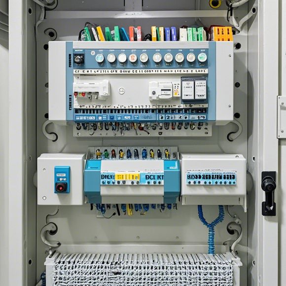
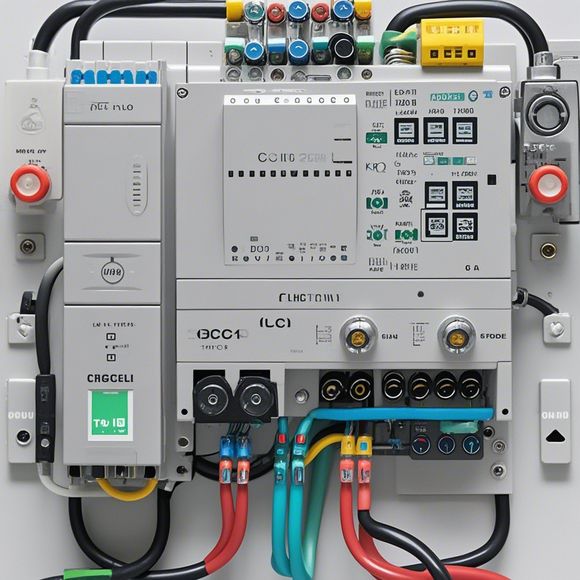
Looking at this PLC control system schematic diagram, it's like reading a roadmap to the inner workings of a highly efficient automation process. The diagram portrays the interconnected components that form the core of any modern industrial machinery or equipment. Let's delve into each element to understand its role and how they work together.
Starting at the heart of the system, the Programmable Logic Controller (PLC) stands out as the brain of the operation. It receives input signals from various sensors and switches, interprets them, and then sends out the appropriate output signals to control the actuators and other devices in the system. The PLC's ability to process these signals quickly and accurately is crucial for efficient operation.
Moving on to the inputs, we have sensors that detect changes in the environment or conditions of the machinery. These sensors send signals to the PLC, providing real-time data on temperature, pressure, motion, and other parameters. This information is vital for the PLC to make informed decisions about the system's performance.

Then there are the output devices, which are controlled by the PLC based on the input signals and the programmed logic. These could be motors, solenoids, or any other equipment that needs precise control. The diagram shows how these devices are connected to the PLC and how their operation is synchronized with the entire system.
The communication links between the PLC and other devices are also crucial. Modern PLC systems use various communication protocols to exchange data with other PLCs, computers, or human-machine interfaces (HMI). This ensures seamless integration with other systems and allows for remote monitoring and control capabilities.
The power supply section is equally important as it ensures stable power delivery to all components. The diagram clearly indicates where power enters the system, how it's distributed, and where critical components are connected to ensure uninterrupted operation.
Lastly, safety features are always a top priority in any control system. The schematic diagram shows how safety switches and interlocks are integrated into the system to prevent accidents or damage due to unauthorized access or malfunctioning equipment.
Overall, this PLC control system schematic diagram provides a comprehensive view of how all components work together to ensure efficient and safe operation. It's a valuable tool for engineers, technicians, and anyone involved in maintaining or troubleshooting these systems. By understanding this diagram, you're well on your way to understanding the inner workings of modern industrial automation.
Articles related to the knowledge points of this article:
How to Use a PLC Controller for Your Business
PLC (Programmable Logic Controller) Control System Basics
Plumbers Rule! The Role of PLC Controllers in the World of Waterworks
The Role of Programmable Logic Controllers (PLCs) in Foreign Trade Operations
Connecting a PLC Controller to Your Computer
PLC Controllers: A Comprehensive Guide to Understanding Their Prices