Mastering the Plumbers Workshop: Understanding the PLC Control Panel Wiring Diagram
Sure, I'd be happy to help you with that. Could you please provide me with the content you have in mind?
In the realm of international trade, understanding the intricacies of the PLC (Programmable Logic Controller) controller's wiring diagram is crucial for ensuring smooth operations and efficient production processes. As a seasoned importer and exporter, I have encountered numerous instances where misunderstandings or incorrect connections led to costly delays or even product recalls. This has prompted me to delve into the in-depth knowledge required to navigate this complex system with precision and accuracy.
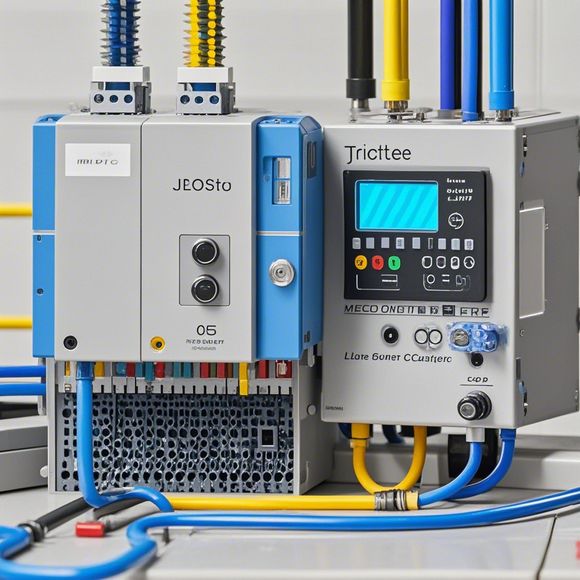
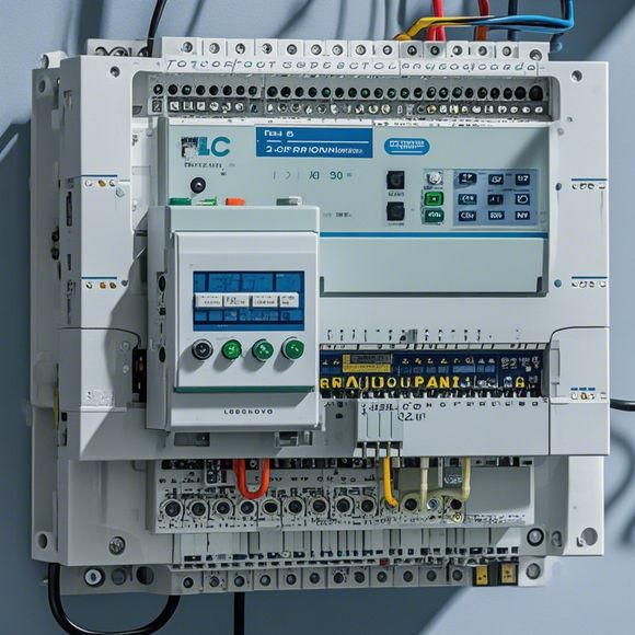
The first step in mastering the PLC controller wiring diagram is familiarizing oneself with its layout and components. A typical PLC control panel consists of several key components, including the CPU (Central Processing Unit), input/output modules, memory, and interface circuitry. Each component plays a distinct role in the overall operation of the PLC, and their placement on the wiring diagram is critical for ensuring seamless communication between them.
One common pitfall many newcomers fall into is not paying close attention to the labelling and symbols used on the diagram. It is essential to understand the meaning of each label and symbol, as they serve as a visual guide to the connections made during assembly. For example, "GND" stands for Ground, "+5V" indicates Power Supply Voltage, and "M1" represents an Input Device. Similarly, "Q0.0" refers to a Output Device, while "I0.0" denotes an Input Device. By familiarizing oneself with these labels and symbols, you can quickly identify the correct connections required for a specific task.
Another essential aspect of understanding the PLC controller wiring diagram is learning how to troubleshoot common issues that may arise during installation or use. Common issues include incorrect connections, faulty components, and improper wiring practices. To address these issues, it is recommended to follow established industry standards and guidelines when performing installations or repairs. Additionally, consulting manufacturer's manuals or online resources can provide valuable insights into common problems and solutions.

In addition to understanding the basics of the PLC controller wiring diagram, it is also important to develop practical skills for troubleshooting and maintenance tasks. This includes learning how to identify and repair common errors such as stuck contacts or broken cables. Furthermore, becoming proficient in using specialized tools and software can significantly enhance the efficiency and effectiveness of the PLC control system.
Ultimately, mastering the PLC controller wiring diagram requires a combination of technical expertise, practical experience, and a deep understanding of the underlying principles governing the system. By following the steps outlined above and consistently refining their knowledge and skills, importers and exporters can confidently navigate the complexities of PLC control systems, leading to increased productivity, reduced downtime, and improved customer satisfaction.
Content expansion reading:
Hello there! As an experienced foreign trade operator, I'm here to guide you through the intricacies of PLC controller wiring diagrams. If you're looking to understand how these diagrams work and how to interpret them, you're in the right place.
First off, let's start with a basic understanding of PLC controllers. PLC, which stands for Programmable Logic Controllers, are industrial-grade devices that monitor and control various processes in manufacturing and automation systems. They are designed to handle digital and analog inputs and outputs, and their wiring diagrams are essential for proper installation and operation.

A PLC controller wiring diagram is a visual representation of how the controller's input and output modules are connected to the field devices. It's important to note that these diagrams can vary depending on the type of PLC and its application. However, there are some common elements that you'll find in most PLC wiring diagrams.
The first thing you'll see in a PLC wiring diagram is the controller itself, which is usually represented by a block or a box. Inside this box, you'll find various input and output modules that connect to the field devices. The input modules receive signals from sensors and other devices, while the output modules send signals to control actuators and other field devices.
The next thing you need to look at is the connection between the PLC and the field devices. These connections are usually represented by wires or cables in the wiring diagram. Each wire represents a specific signal or function, such as a start/stop signal, a limit switch, or a motor control signal. It's important to identify each wire and understand its function to ensure proper installation.
In addition to the basic elements, there may be other details in the wiring diagram that are specific to your application. For example, you may find terminals, relays, filters, or other components that are used to enhance performance or protect the PLC from damage. It's important to understand the purpose of these components and how they fit into the overall system.
Now, let's go through the process of interpreting a PLC wiring diagram. The first step is to identify all the components in the diagram and understand their purpose. Then, you need to trace the wires from the PLC to the field devices and identify each connection point. It's also important to check for any special instructions or notes in the diagram that may provide additional information or guidance.

Once you have a good understanding of the wiring diagram, you can proceed with the installation process. During installation, it's crucial to follow the diagram carefully and ensure that all connections are made correctly. If there are any doubts or uncertainties, it's always best to consult the manufacturer's documentation or seek assistance from an experienced professional.
In summary, PLC controller wiring diagrams are essential for proper installation and operation of PLC systems. By understanding the basic elements of the diagram and following the process of interpretation, you can ensure that your system is installed correctly and operates efficiently. Remember, safety is always a top priority when working with electrical equipment, so make sure to follow all safety guidelines and best practices.
That's it for today! I hope this explanation helped you understand PLC controller wiring diagrams better. If you have any further questions or need assistance with a specific application, feel free to reach out. Happy to help!
Articles related to the knowledge points of this article:
Smart Manufacturing Solutions with PLC Integrated Machinery
PLC Controller Selection Guide for Foreign Trade Operations
Mastering the Art of Plc Controllers: A Comprehensive Guide to Understand and Implement
PLC (Programmable Logic Controller) Control System Basics
Plumbers Rule! The Role of PLC Controllers in the World of Waterworks