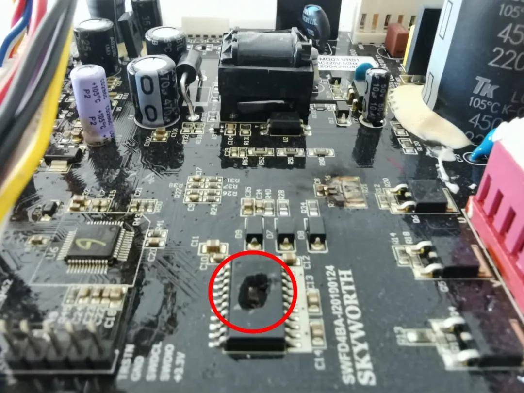
PLC Controller Simple Structure Diagram
The PLC controller simple structure diagram is a visual representation of the basic components and connections within a PLC system. It provides a quick and easy way to understand the overall structure of the system, making it a valuable tool for both designers and operators. The diagram typically includes the PLC processor, input/output modules, communication interfaces, and any other necessary components. It may also show the connections between these components, such as data lines, control lines, and power lines. By examining the simple structure diagram, one can quickly identify the core elements of the PLC system and understand how they interact with each other to control the process or machine being monitored.
PLC, which stands for Programmable Logic Controller, is a digital computer used for automation. It is a key component of industrial control systems, performing the function of a brain in a larger machinery system. The PLC controller is designed to monitor and control the operation of machines and processes, ensuring that they run smoothly and efficiently.
A simple structure diagram of a PLC controller is composed of three main components: the Central Processing Unit (CPU), the Program Memory (PM), and the Input/Output (I/O) Modules. The CPU is responsible for executing the program stored in the PM and processing the data received from the I/O Modules. The PM stores the program written by the user, which defines the logic and control sequences for the system. The I/O Modules are connected to the sensors and actuators of the machinery system, providing a interface between the PLC controller and the real-world devices.

In addition to these three main components, a PLC controller also includes a power supply, a display unit, and various interface cables and connectors. The power supply provides the necessary electrical energy to power the PLC controller and its connected devices. The display unit, which may be a simple LED display or a more complex touchscreen interface, allows the operator to monitor the status of the system and make adjustments as needed. The interface cables and connectors are used to connect the PLC controller to other devices, such as computers or sensors, allowing it to receive input data and send control signals to those devices.
The PLC controller operates in a cyclical fashion, continuously monitoring the inputs from the I/O Modules and executing the program stored in the PM to determine the appropriate output signals to send to the actuators. This process of input processing and output control is repeated over and over again, allowing the system to respond to changes in the environment or operator commands.
One of the key features of a PLC controller is its ability to store and execute programs written in a specialized programming language called ladder logic or structured text. These programs define the logic of the system, specifying how inputs are to be interpreted and what actions are to be taken based on those inputs. The PLC controller can also store data, allowing it to keep track of system variables and states over time.

In conclusion, a PLC controller is a crucial component of industrial automation systems, providing the intelligence and flexibility to monitor and control complex machinery operations. Its simple structure diagram outlines the basic components and operations of a PLC controller, illustrating how it interfaces with the real-world devices and processes data to control the system effectively.
Articles related to the knowledge points of this article:
PLC Programmable Controller Prices: A Comprehensive Guide
PLC Controller Factory Settings
PLC Controllers and Electromagnetic Valves: Understanding Their Roles and Interactions