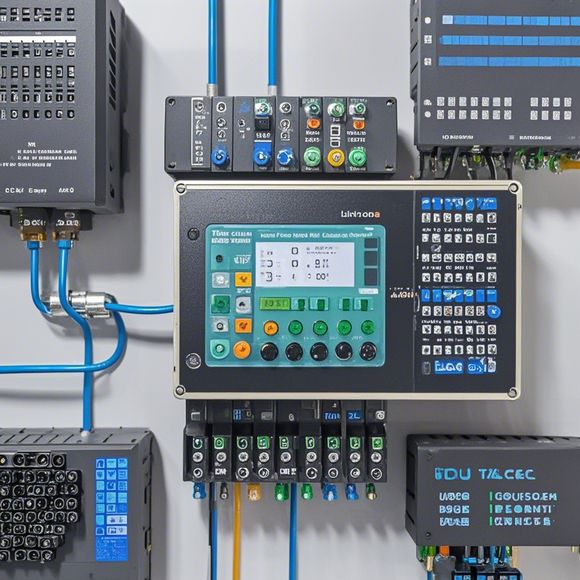
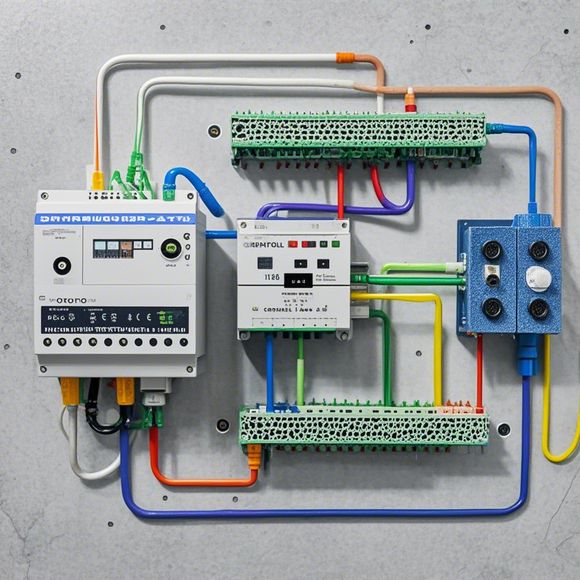
PLC Control Cabinet Wiring Diagram Overview for Foreign Trade Operations
Sure, here's a summary in English that you can use for your PLC (Programmable Logic Controller) Control Cabinet wiring diagram overview:Foreign trade operations typically rely on the precise and efficient management of electrical connections. This involves understanding how to properly wire various components such as sensors, switches, relays, and motors, all controlled by the PLC. The diagram provided will outline the essential steps involved in setting up these connections, including the placement of the PLC, the connection of sensors or other devices, the wiring of control circuits, and the configuration of safety features to ensure safe and reliable operation. By following this diagram, businesses can streamline their foreign trade operations, reduce costs, and improve operational efficiency.
Dear colleagues,

I hope this message finds you well. As we navigate through the complexities of global trade and the ever-evolving landscape of international markets, it is crucial for us to have a comprehensive understanding of how PLC (Programmable Logic Controller) control cabinets are wired. This is particularly important when dealing with foreign clients or partners, as it ensures that our products are delivered with precision and reliability.
Let's delve into the intricacies of PLC control cabinet wiring diagrams. A PLC control cabinet serves as the central nervous system of a manufacturing or industrial operation, controlling and regulating various processes based on predefined logic and commands. The wires that connect these components play a crucial role in ensuring that the cabinet operates efficiently and reliably.
At its core, a PLC control cabinet consists of three major components: the input/output modules (I/O modules), the processor unit, and the communication interface. The I/O modules are responsible for receiving data inputs from sensors, actuators, and other devices, and for sending output signals to control valves, motors, and other machinery. The processor unit interprets the data received by the I/O modules and executes the corresponding commands to perform the desired function. Finally, the communication interface allows the PLC to communicate with other systems such as computers, printers, and alarm systems.
Now, let's talk about the wiring diagram. A wiring diagram is a detailed representation of the connections between different components in a PLC control cabinet. It shows the sequence of wires that connect each component, indicating which pins are connected together, and what functions they perform. A good wiring diagram not only helps technicians troubleshoot issues but also provides valuable information for designers to ensure that the circuit is optimized for performance and safety.
To illustrate this concept with an example, consider a simple PLC control cabinet with two I/O modules and a processor unit. The wiring diagram would show the following connections:

1、I/O module A - Input pins (1-2) - Connected to Input pins (A-B) - Processor Unit - Output pins (C-D) - Connected to Actuator
2、I/O module B - Input pins (E-F) - Connected to Input pins (G-H) - Processor Unit - Output pins (I-J) - Connected to Motor
3、Communication interface - Connected to Computer
In this example, pins A-B represent the inputs received from sensors or other devices, while pins A-B represent the outputs sent to control valves or motors. Pin C-D represents the processor unit's processing power, while pin D-E represents the execution of commands based on the data processed. Pin F-H represents the output signals sent to the actuator, while G-H represents the output signals sent to the motor. Finally, Pin I-J represents the output signals sent to the external communication interface for further processing or display.
Of course, the actual wiring diagram can be much more complex, involving many different types of wires, connections, and protocols. However, the key takeaway is that a well-designed and accurate wiring diagram is essential for ensuring that the PLC control cabinet operates smoothly and reliably.

In conclusion, let me reiterate the importance of having a thorough understanding of PLC control cabinet wiring diagrams. They are not just technical documents; they are critical tools for ensuring that our products meet the needs of foreign clients or partners. So let's embrace this knowledge, refine our skills, and strive to provide unmatched customer service through our exceptional product offerings. Thank you for your attention, and happy learning!
Content expansion reading:
Articles related to the knowledge points of this article:
PLC Controller Selection Guide for Foreign Trade Operations
PLC Controller for Manufacturing Automation
The cost of a PLC Controller: A Comprehensive Analysis
PLC Programming for Automation Control in the Manufacturing Industry